
Method for measuring thickness of measured article and its device

A measurement method and a technology of a measurement device, which are applied in the field of thickness measurement of transparent sheets, can solve problems such as inability to obtain point data, difficulty in maintenance, and unstable measurement.

Inactive Publication Date: 2002-11-27
日本マクシス
View PDF4 Cites 19 Cited by
  • Summary
  • Abstract
  • Description
  • Claims
  • Application Information

AI Technical Summary

Problems solved by technology

[0010] (1) Since it is necessary to measure the light intensity for each rotation angle multiple times (four times in the embodiment) while rotating the detector in sequence, point data cannot be obtained at one time, so high-speed measurement cannot be performed
Especially in the case of TV5 (Thickness Variation Five Points), which is required for crystal flakes, five point data must be measured, so it is difficult to achieve high speed
[0011] (2) Due to the existence of mechanical mechanisms such as motors, gears, and encoders, maintenance is difficult, and special control systems such as peripheral circuits of the control mechanism are required
[0012] (3) Since the amount of information obtained at one time is small, if there is an error, it is difficult to remove the error, and high-precision measurement cannot be performed
[0013] (4) Since the thickness is measured using the intensity of light, it is affected by light attenuation caused by changes in light intensity and the thickness of the object to be measured, and the measurement is unstable.
[0014] (5) Since the detection is performed by a photodetector rather than an imager, when the processing accuracy of each component of the device changes, it is difficult to correct, and it is impossible to correct the mechanical defects of each component of the device
[0015] (6) Since a part of the device (circular plate 12 and gear 13) is a contact type, it is easy to damage or contaminate the object to be measured, and it is also difficult to install the centering device, and the workability is poor.

Method used


Image

  • Method for measuring thickness of measured article and its device
  • Method for measuring thickness of measured article and its device
  • Method for measuring thickness of measured article and its device

Examples


Embodiment

[0084] Next, an example in which the method for measuring the thickness of the object to be measured and the device thereof is applied to a single crystal wafer for a surface acoustic wave device will be described. Figure 14 and Figure 15 It is a plan view and a side view of the SAW wafer inspection device.

[0085] Figure 14 In the SAW wafer inspection apparatus, a transfer chamber 51 for transferring wafers is arranged in the center, an inspection chamber 52 for inspecting wafers W is arranged inside the transfer chamber 51, and a console 53 for operating the control device is arranged in front of the transfer chamber.

[0086] The transfer chamber 51 has a wafer transfer robot 54 provided in the center and cassettes 55 provided on the left and right sides of the wafer transfer robot 54 . The wafer transfer robot 54 pulls out the wafer W before inspection from the wafer cassette 56 and transfers it to the inspection chamber 52, and transfers the inspected wafer W after ...


PUM

PropertyMeasurementUnit
Surface roughnessaaaaaaaaaa

Abstract

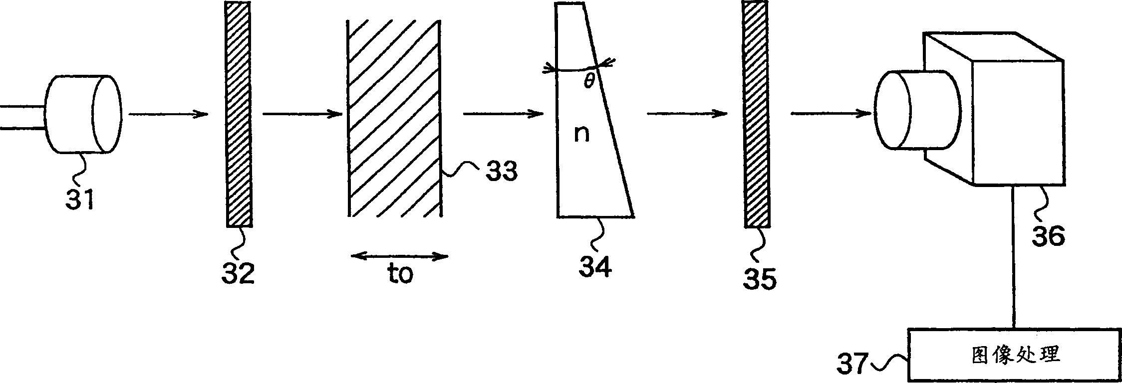
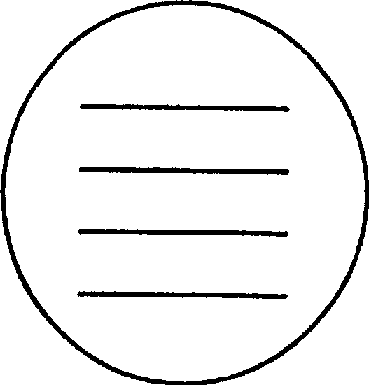
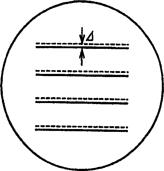
A method and device for measuring the thickness of a measured object, which can perform high-speed, high-precision, stable measurement and are easy to maintain. The coherent light emitted from the light source 31 is converted into the desired linearly polarized light by the polarizer 32, and the linearly polarized light is incident on the object 33 having birefringence, and the normal light and the extraordinary light are taken out, and the taken out light is further incident on the wedge shape. The prism 34 extracts the light having a phase difference that changes according to the thickness of the measured object 33 and the wedge prism 34 that passes through the measured object 33 at the measurement site. The light taken out is received by the analyzer 35, and a component of a polarization direction is extracted from the normal light and the extraordinary light, and the interference of the normal light component and the extraordinary light component of a polarization direction is generated, and the generated interference is reflected on the camera as interference fringes. By observing the reflected interference fringes on the screen of the device 36, the image processing device 37 measures the thickness of the object 33 depending on the displacement of the interference fringes.

Description

technical field [0001] The invention relates to a method and device for measuring the thickness of an object to be measured, in particular to a method for measuring the thickness of birefringent transparent sheets such as crystals. Background technique [0002] Conventionally, an optical plate thickness measuring device for measuring the thickness of a substrate having birefringence has been disclosed (for example, Japanese Patent Application Laid-Open No. 9-292208). Such as Figure 18 As shown, the optical plate thickness measurement device includes: a laser light source 2 for generating laser light; a polarizer 3, which converts the laser light emitted from the laser light source 2 into desired linearly polarized light and enters the measured substrate 4; a detector 7, A component of a polarization direction is extracted from the laser light passing through the measured substrate 4; a photodetector 8 detects the light intensity of the laser light e...

Claims


Application Information

Patent Timeline
IPC IPC(8): G01B11/06
Inventor 小林了高桥升
Owner 日本マクシス
Learn More