Method and appts. for reducing discharge of nitrogen oxide in selective catalytic reduction system

A technology of equipment and reducing agent, which is applied in the direction of chemical instruments and methods, separation methods, mechanical equipment, etc., can solve the problems of solidified storage tank liner pumps, damage, unacceptable evaporative emissions, etc., and achieve the effect of eliminating the loss of reducing agent

Inactive Publication Date: 2002-12-04
HALDOR TOPSOE AS
View PDF3 Cites 14 Cited by
  • Summary
  • Abstract
  • Description
  • Claims
  • Application Information

AI Technical Summary

Problems solved by technology

[0021] and currently used to reduce NO x Some of the problems associated with SCR systems are corrosion of different components in the system, urea crystallization leading to deposits in the lines, maintaining constant valve setting

Method used


Image

  • Method and appts. for reducing discharge of nitrogen oxide in selective catalytic reduction system
  • Method and appts. for reducing discharge of nitrogen oxide in selective catalytic reduction system
  • Method and appts. for reducing discharge of nitrogen oxide in selective catalytic reduction system

Examples


Embodiment 1

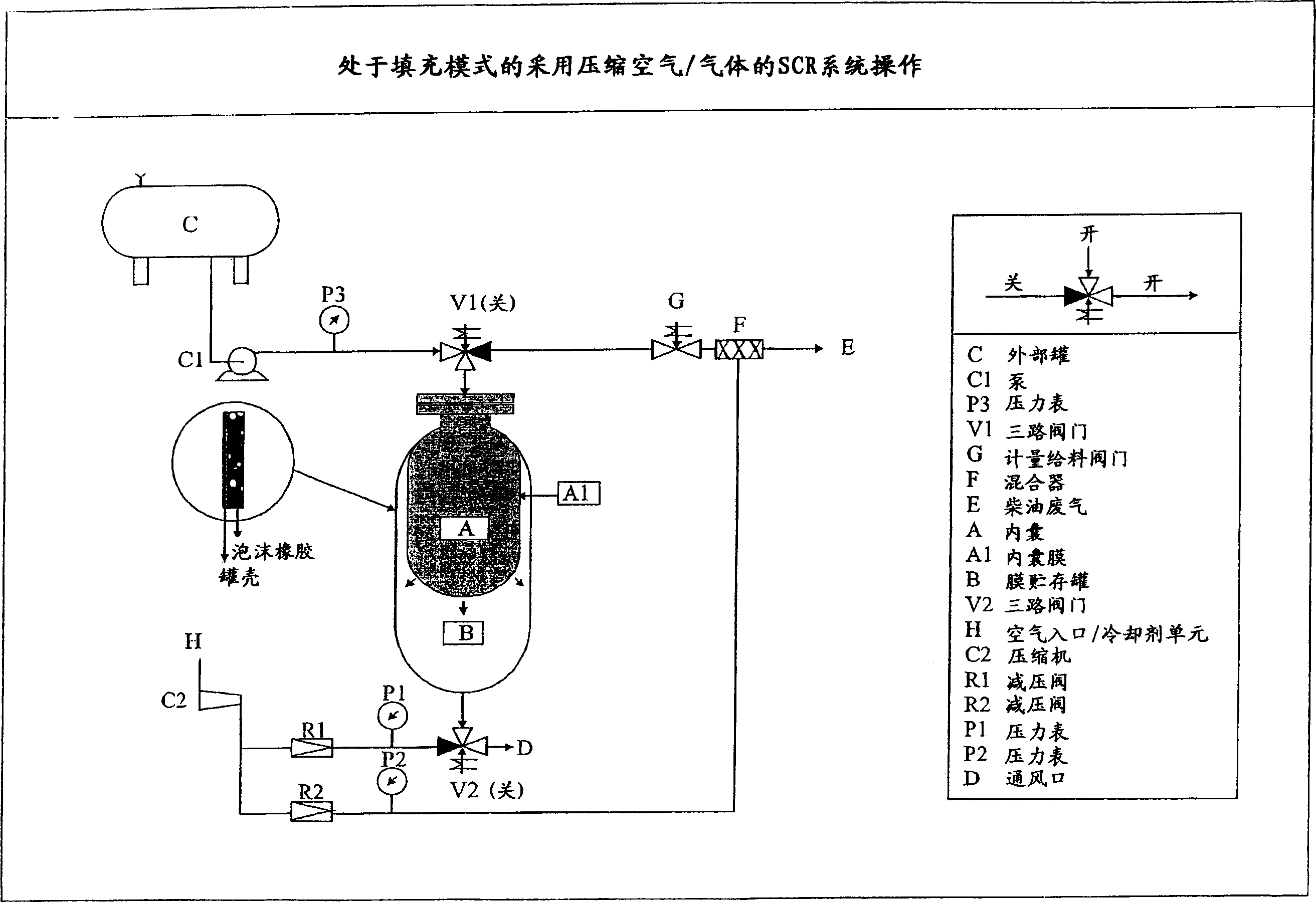
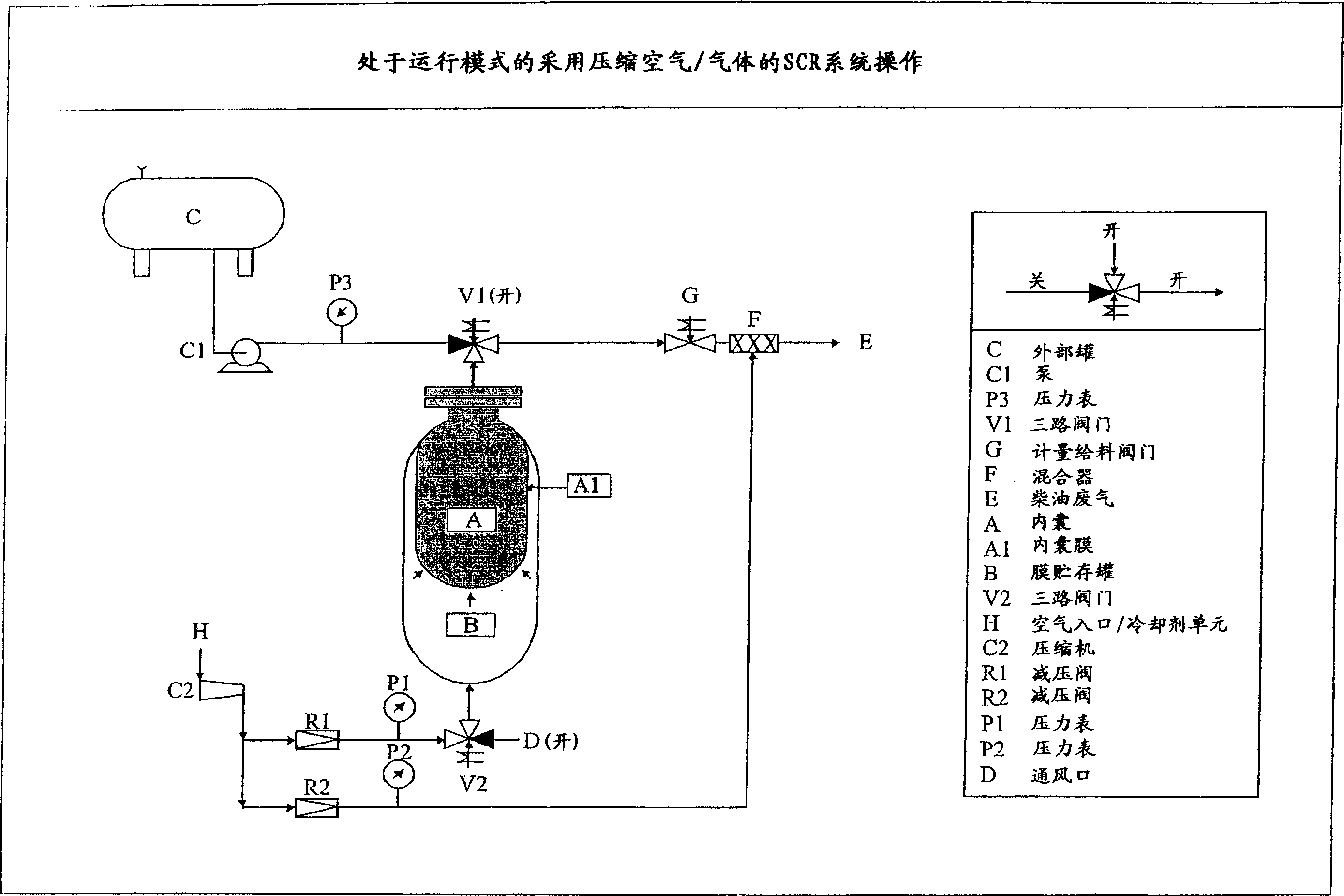
[0068] Build and test a system as described above. The inner capsule A was filled with a 32.5 wt / wt% aqueous urea solution. Turn valves V1 and V2 to "open" position (running mode). Adjust the pressure regulator R1 to 2 bar (2×10 5 Pa). The carrier air entering the mixer F is adjusted to 1 bar (1×10 5 Pa). By actuating the dosing valve G, a constant urea flow into the exhaust gas E is established. Example 2

Embodiment 2

[0069] Fill inner capsule A with 25% ammonia water instead of urea solution. The pressure setting is identical to Example 1. A constant ammonia flow is established by actuating the dosing valve G.

Embodiment 3

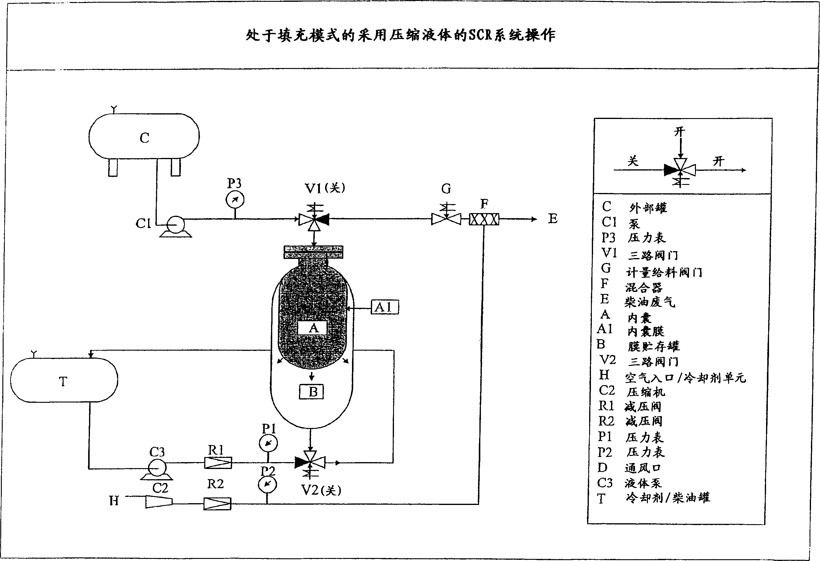
[0071] As Example 1, but in this case coolant liquid from tank T is used instead of compressed air. The coolant is pumped out via pump C3. On the pressure reducing valve R1, adjust the flow pressure to 2 bar (2×10 5 Pa). Liquid flow is delivered to tank B through V2 in the "on" position. Compress the urea contained in inner capsule A to 2 bar (2×10 5 Pa) equivalent pressure. As in Example 1, the flow of urea into mixer F was established.


PUM


Abstract

The present invention relates to a method and apparatus for reducing nitrogen oxides in exhaust gases of diesel engines or turbines for stationary or mobile applications/vehicles in SCR systems by providing a stored source of liquid reductant and feeding the stored reductant into the exhaust gas (NOx) content, the method comprising transferring a liquid reductant from an external storage tank to a membrane storage tank equipped with an inner bladder composed of an impermeable flexible membrane and a hydraulic or pneumatic displacement fluid located outside the inner bladder, reducing with the liquid The reductant is filled with the flexible inner bag, and the liquid reductant is delivered from the flexible inner bag to the exhaust gas.

Description

technical field [0001] The invention relates to a method for reducing nitrogen oxides (NOx) in the exhaust gas of fixed or mobile diesel engines or turbines x ) emissions, and more particularly to a method applicable to a selective catalytic reduction (SCR) system. [0002] Said SCR systems are a known and widely distributed technology used in heavy industry for the removal of nitrogen oxides in the exhaust gases of turbines, boilers, burners, power generation plants and other plants using fossil fuels. The system is based on the presence of NO in the exhaust x In the presence of the compound, a reducing atmosphere is established on the catalyst. [0003] The choice of reductant depends on the locally prevailing conditions in the different geographic regions where the SCR system will be used. Conditions such as price, regulations, and logistics play a role in the choice of reducing agent. The reducing agent usually used with diesel engine is pure ammonia or ammonia water (...

Claims


Application Information

Patent Timeline
IPC IPC(8): F01N3/08B01D53/94F01N3/00F01N3/20F04B9/08F04B43/10
CPCB01D53/9404F01N3/2066F01N2610/02F01N2610/03F01N2610/08F01N2610/14F01N2610/1406Y02A50/20Y02T10/12
Inventor S·-E·米克尔森P·L·T·加布里尔松
Owner HALDOR TOPSOE AS
Why Eureka
Try Eureka