Illumination system, light mixing chamber and dispaly device

A lighting system and display device technology, applied in the field of lighting systems, can solve the problems of insufficient illumination uniformity and insufficient light distribution of the display device, etc.

Inactive Publication Date: 2002-12-04
LUMILEDS HLDG BV
View PDF1 Cites 16 Cited by
  • Summary
  • Abstract
  • Description
  • Claims
  • Application Information

AI Technical Summary

Problems solved by technology

[0011] A disadvantage of lighting systems of the type described above is that the distribution of light within the luminous panel, especial

Method used


Image

  • Illumination system, light mixing chamber and dispaly device
  • Illumination system, light mixing chamber and dispaly device
  • Illumination system, light mixing chamber and dispaly device

Examples


Embodiment Construction

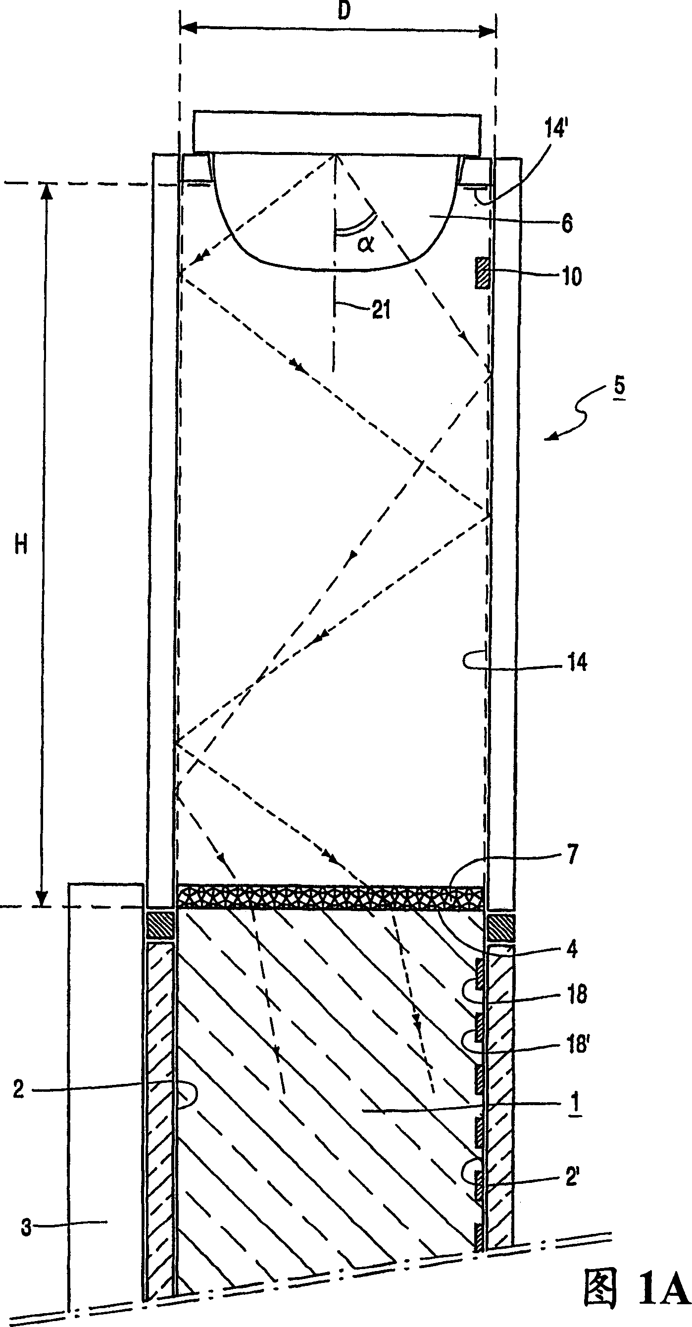
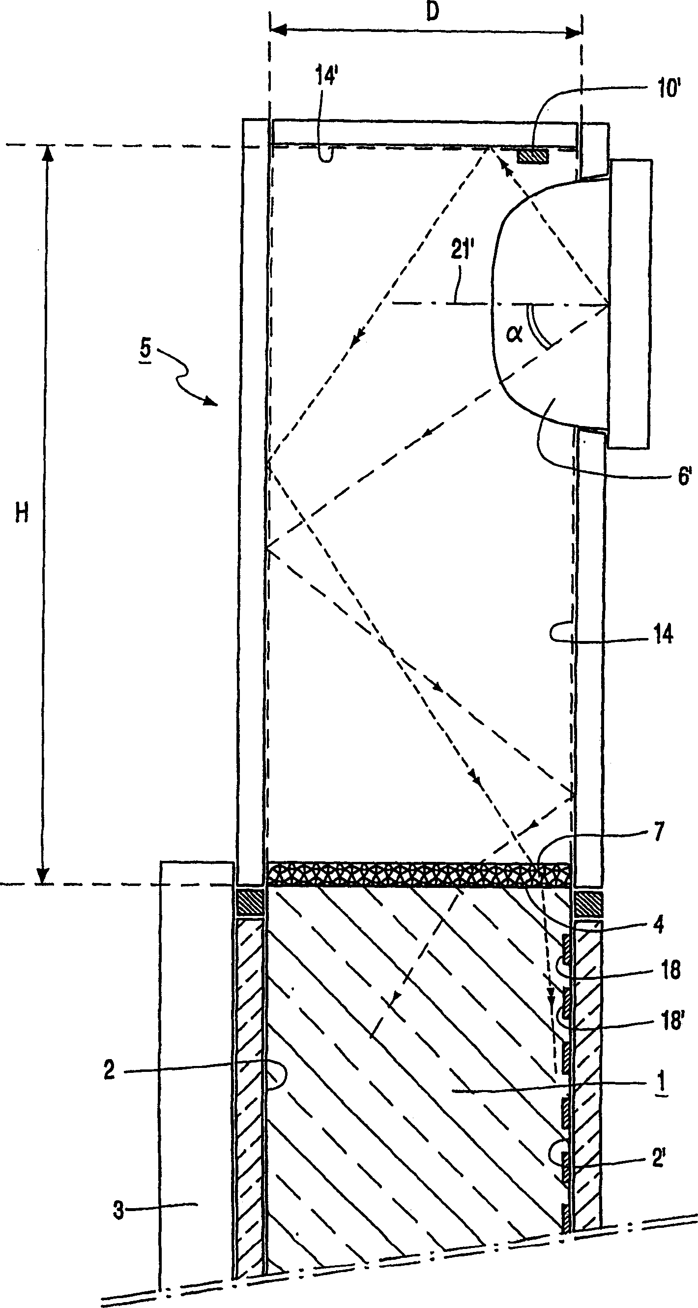
[0066] Figure 1A is a schematic cross-sectional view of an assembly of a lighting system and a display device, which includes an embodiment of a lighting system according to the present invention. The lighting system comprises a light-emitting panel 1 of light-transmitting material. For example, the plate 1 can be made of synthetic resin, acrylate, polycarbonate, PMMA (polymethyl methacrylate) such as Perspex, or glass. In operation, light propagates through the plate 1 under the effect of total internal reflection. The luminous panel 1 has a light emission window 2 and a rear wall 2' opposite the light emission window. Between the light emission window 2 and the rear wall there is a light coupling edge region 4 for coupling light into the luminous panel 1 . The lighting system also includes a longitudinal 15 (see image 3 ) of the light mixing chamber 5, and the lighting system is provided with a light source 6 having a longitudinal axis 21. The light mixing cavity 5 has ...


PUM


Abstract

A backlight system for illuminating a display device (3) comprises a luminous panel (1) having a light emission window (2) and at least one edge face (4) coupling light into the luminous panel (1). The backlight system also includes a light mixing cavity (5) equipped with a light source (6). The light mixing cavity (5) is connected to the edge surface (4). According to the invention, the light source (6) comprises a plurality of clusters of light emitting diodes (LEDs) having different light emission wavelengths, the clusters being arranged at a distance P between each other. The ratio of the height H of the optical mixing cavity (5) to the cluster pitch P satisfies the relationship 0.1≤H/P≤10, preferably 0.2≤H/P≤2. Each cluster preferably includes one blue, one green and one red LED or one blue, two green and one red LED. Preferably each LED has a luminous flux of at least 5 lumens. The backlight system of the present invention has a very uniform light distribution, so that the display device is evenly illuminated.

Description

technical field [0001] The invention relates to a lighting system for illuminating a display device comprising: [0002] a luminescent panel having a light emission window and at least one light coupling edge region for coupling light into the luminescent panel; and [0003] The light mixing cavity, which extends longitudinally parallel to the light coupling edge region, has a light source and is connected to the light coupling edge region. [0004] The invention also relates to a light mixing cavity for a lighting system. [0005] The invention also relates to a display device comprising said lighting system. technical background [0006] Such lighting systems are known per se, also known as edge lighting systems. One of their uses is as backlighting for (picture) display devices such as television receivers and monitors. Such lighting systems are particularly suitable as backlights for non-emissive displays, such as liquid crystal display devices, also called LCD panel...

Claims


Application Information

Patent Timeline
IPC IPC(8): G02F1/13357F21V8/00F21V23/04F21Y115/10G02B6/00G02F1/1335
CPCF21V23/0442F21Y2115/10G02B6/0033G02B6/0068G02F1/133615Y10S362/80G02F1/1335
Inventor C·G·A·霍埃伦G·哈伯斯
Owner LUMILEDS HLDG BV
Why Eureka
Try Eureka