Fuel jetting controller for internal combustion engine
A technology of control device and fuel injection, which is applied in the direction of fuel injection device, fuel injection control, engine control, etc., and can solve problems such as deterioration of restartability at high temperature, deterioration of restartability, failure to deliver fuel, etc.
- Summary
- Abstract
- Description
- Claims
- Application Information
AI Technical Summary
Problems solved by technology
Method used
Image

Examples
Embodiment 1
[0038] Hereinafter, Embodiment 1 of the present invention will be described in detail with reference to the drawings.
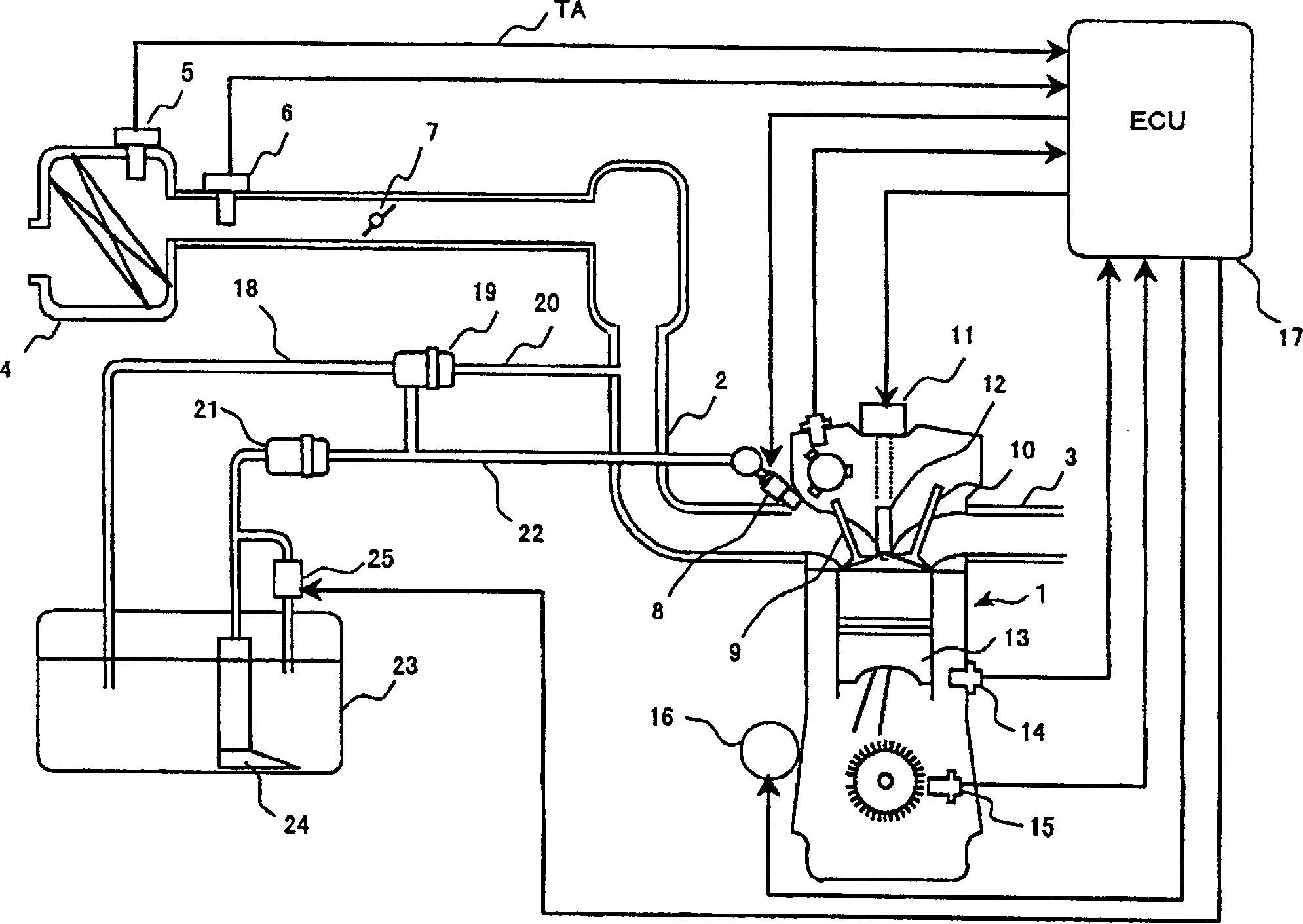
[0039] figure 1 It is a schematic structural diagram of Example 1 of the present invention.
[0040] in figure 1 In the engine 1, an intake pipe 2 for introducing intake air and an exhaust pipe 3 for guiding exhaust gas after combustion are provided.
[0041] The intake pipe 2 is provided with an air filter 4, an intake air temperature sensor 5, an air flow sensor 6, a throttle valve 7 and a nozzle 8 from the upstream side.
[0042] The intake pipe sensor 5 detects the intake air temperature of the engine 1, and the air flow sensor 6 detects intake air amount information corresponding to the intake air amount introduced into the engine 1.
[0043] The throttle valve 7 adjusts the amount of intake air to the engine 1, and the nozzle 8 injects fuel on the upstream side of the engine 1.
[0044] Contains an ECU (Electronic Control Device) 17 and a microcomputer t...
Embodiment 2
[0088] In the first embodiment described above, the control of the starter 16 when the engine is started is not mentioned, but a delay time corresponding to the increase in fuel pressure when the starter 16 is driven may be set.
[0089] The following reference figure 1 as well as Figure 7 with Figure 8 The second embodiment of the present invention in which the starter 16 is controlled with a delay in starting will be described.
[0090] As described above, the starter 16 has a structure that can be directly turned on / off (ON / OFF) by the ECU 17.
[0091] Figure 7 and Figure 8 It is a block diagram and a time chart of the starter control process at the time of engine start in the second embodiment of the present invention.
[0092] in Figure 8 Here, the predetermined delay time TD from when the ignition switch is turned on (ON) to when the starter 16 is turned on (ON) is set to the time until the fuel pressure is sufficiently increased.
[0093] in Figure 7 At first, ECU17...
PUM
 Abstract
Description
Claims
Application Information
 - R&D
- Intellectual Property
- Life Sciences
- Materials
- Tech Scout
- Unparalleled Data Quality
- Higher Quality Content
- 60% Fewer Hallucinations
Browse by: Latest US Patents, China's latest patents, Technical Efficacy Thesaurus, Application Domain, Technology Topic, Popular Technical Reports.
© 2025 PatSnap. All rights reserved.Legal|Privacy policy|Modern Slavery Act Transparency Statement|Sitemap|About US| Contact US: help@patsnap.com