Faraday device

A Faraday cup and positive bias technology, which is applied in the direction of measuring devices, irradiation devices, instruments, etc., can solve problems such as errors

Inactive Publication Date: 2002-12-11
NISSIN ION EQUIP CO LTD
View PDF0 Cites 5 Cited by
  • Summary
  • Abstract
  • Description
  • Claims
  • Application Information

AI Technical Summary

Problems solved by technology

[0010] As a result, the Faraday cup 12 measures a portion of the ions 22 of the plasma 20 in addition to the beam current of the ion beam 2 that was originally to be measured, thus causing an error in the beam current

Method used


Image

  • Faraday device
  • Faraday device
  • Faraday device

Examples


Embodiment Construction

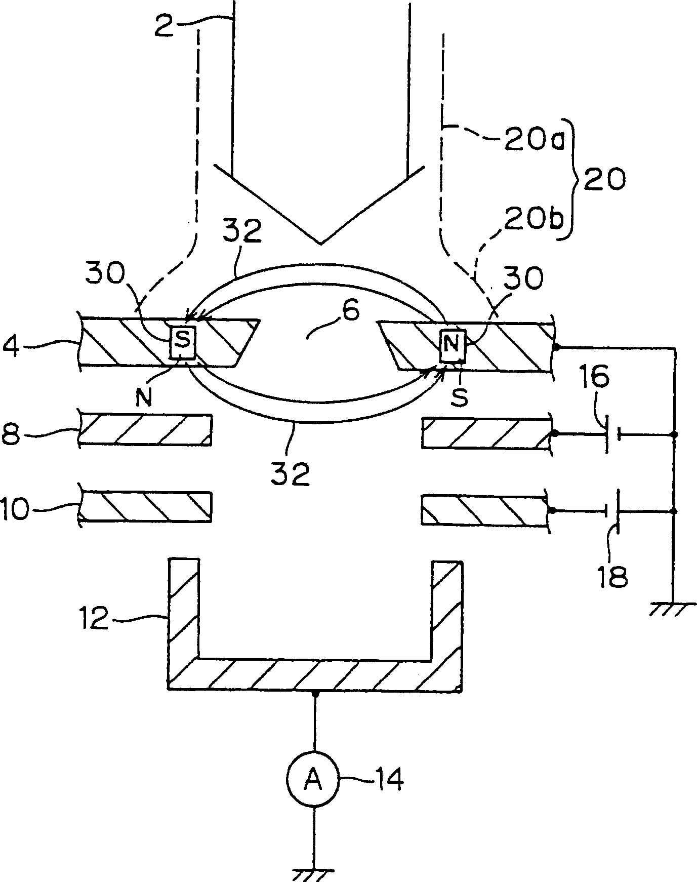
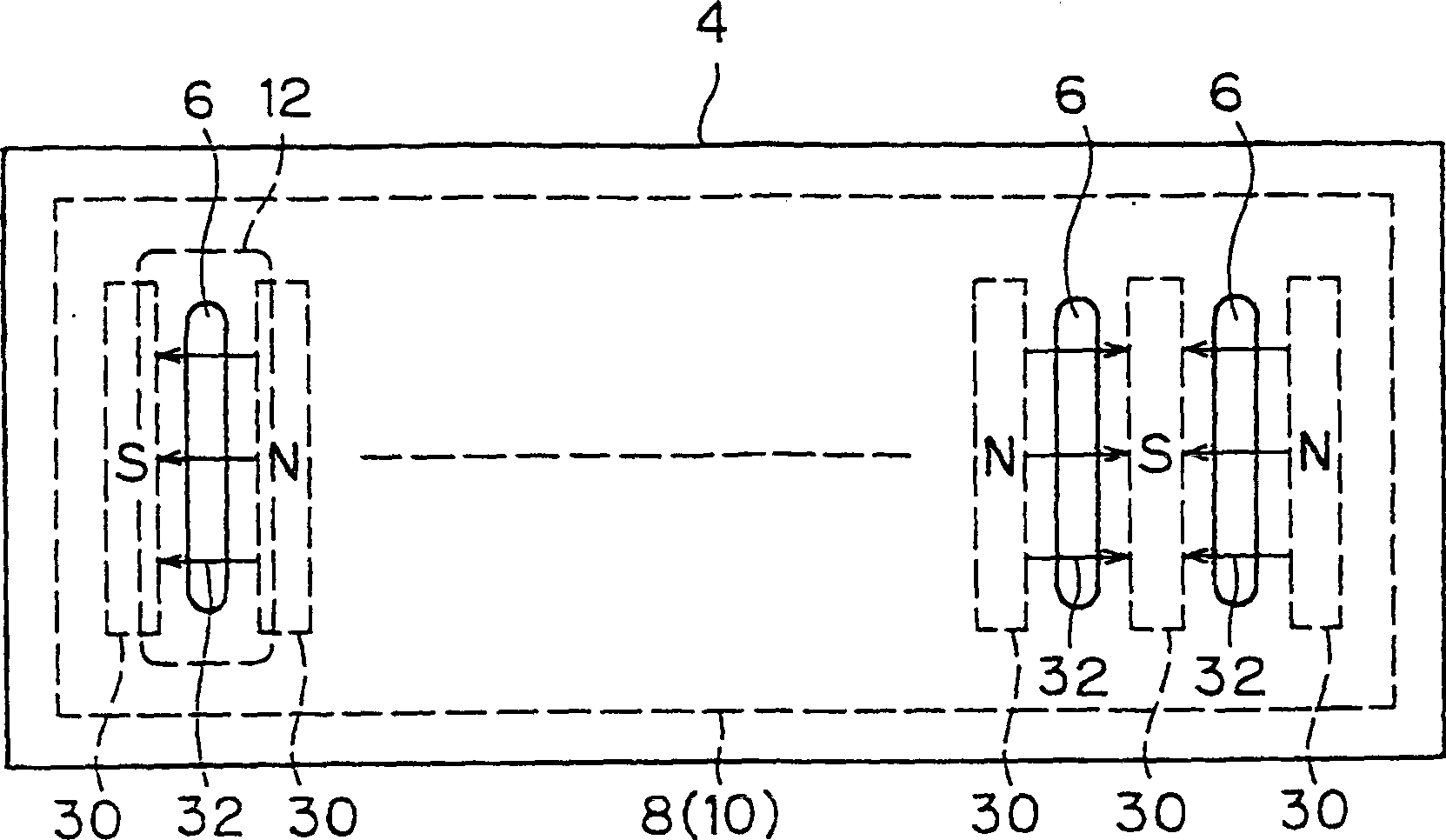
[0019] figure 1 is a cross-sectional view of a Faraday device according to the present invention. figure 2 is the floor plan of the Faraday device. In the picture with Figure 5 Like parts of the prior art shown are designated with like reference numerals. The description will mainly focus on the different parts.

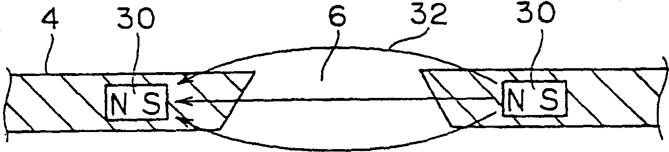
[0020] In the Faraday device of the present invention, a pair of magnets 30 are hidden in the baffle 4, and the polarities of the two magnets are opposite. The magnet 30 is arranged across the aperture 6 of the baffle 4 . Magnets 30 generate a magnetic field in the vicinity of the aperture of baffle 4 , which is distributed across aperture 6 . The flux lines of the magnetic field are indicated by reference numeral 32 .

[0021] While it is not always necessary in this embodiment to hide the magnet 40 in the mask 4, it is preferable to hide the magnet 30 because then the ion beam 2 and plasma 20 do not have the opportunity to strike the magnet 30 and sputter t...


PUM


Abstract

A Faraday device has magnets for developing a magnetic field having a direction crossing an aperture of a mask in the vicinity of the aperture.

Description

technical field [0001] The present invention relates to a Faraday device for measuring ion beam current in ion emitters, ion doping devices (non-mass separation type ion emitters), ion beam radiation devices and the like. More particularly, it relates to a Faraday device capable of reducing beam current measurement errors caused by ions contained in the plasma entering the Faraday cup. In this specification, the term "ion" refers to positive ions. technical background [0002] Figure 5 Indicates a Faraday device of related art. The Faraday device comprises a baffle 4 , a Faraday cup 12 , a suppressor electrode 10 and a positive bias electrode 8 . The mask 4 has an aperture 6 for limiting the area (shape) of the ion beam 2 passing through the aperture 6 . The Faraday cup 12 receives the ion beam 2 that has passed through the aperture 6 and measures the beam current of the ion beam. The suppressor electrode 10 is provided in the vicinity of the Farad...

Claims


Application Information

Patent Timeline
Patent Type & Authority Applications(China)
IPC IPC(8): G21K5/04G01R19/00G01T1/29H01J37/04H01J37/244H01J37/30H01J37/317H01L21/265
CPCH01J37/3171
Inventor 井内裕前野修一安东靖典松田恭博
Owner NISSIN ION EQUIP CO LTD
Why Eureka
Try Eureka