Heat insulation container and its producing method

A manufacturing method and container technology, which is applied in the direction of heat-insulating containers, chemical instruments and methods, containers, etc., and can solve the problems that the radiant heat prevention film cannot be configured and the performance cannot be satisfied.

Inactive Publication Date: 2003-01-01
NIPPON SANSO CORP
View PDF2 Cites 8 Cited by
  • Summary
  • Abstract
  • Description
  • Claims
  • Application Information

AI Technical Summary

Problems solved by technology

Also, since the firing is carried out at high temperature, the radiant heat prevention film cannot be placed in the heat-insulating space layer, and there is a problem that the performance cannot be satisfied.

Method used


Image

  • Heat insulation container and its producing method
  • Heat insulation container and its producing method
  • Heat insulation container and its producing method

Examples


Embodiment Construction

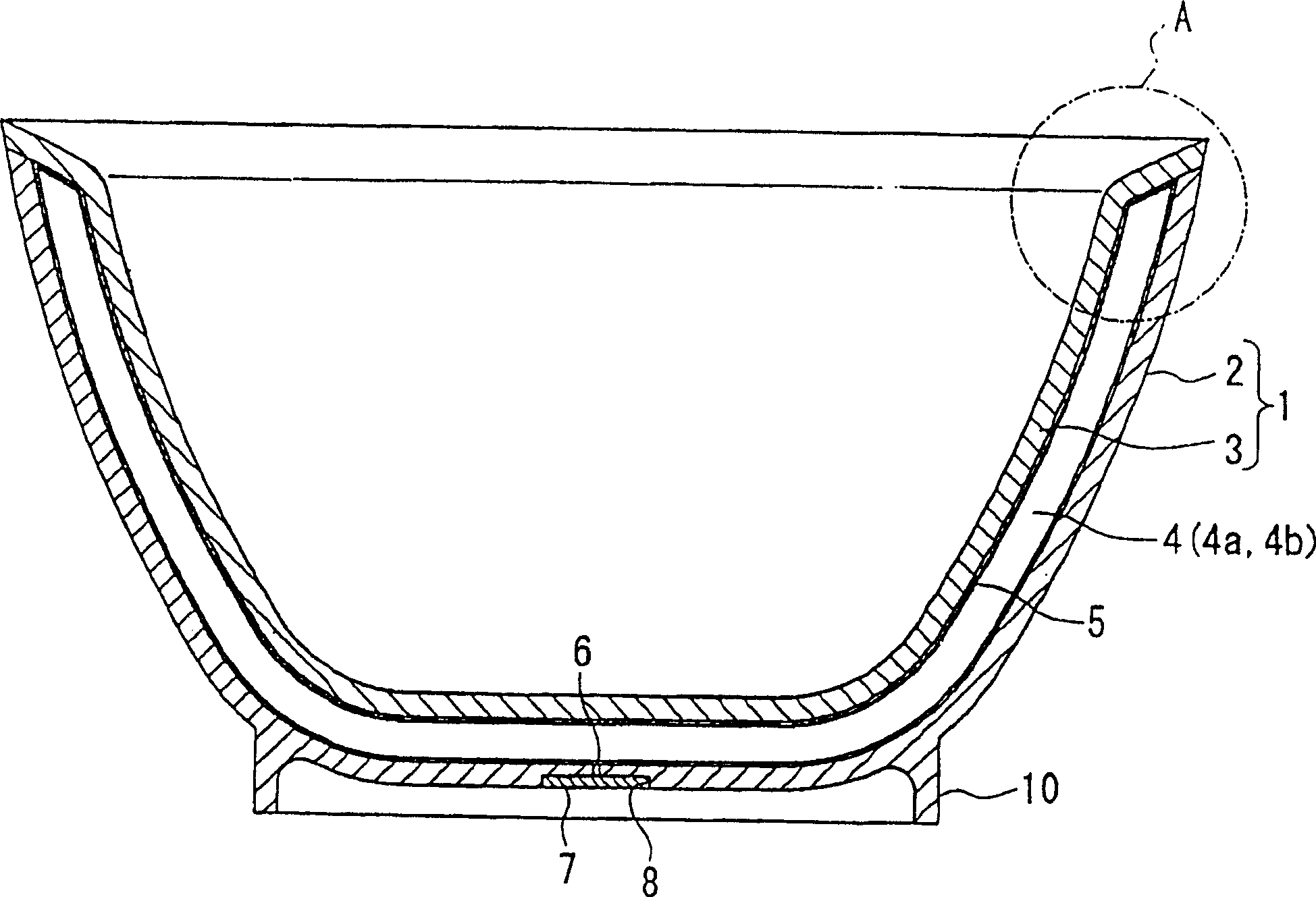
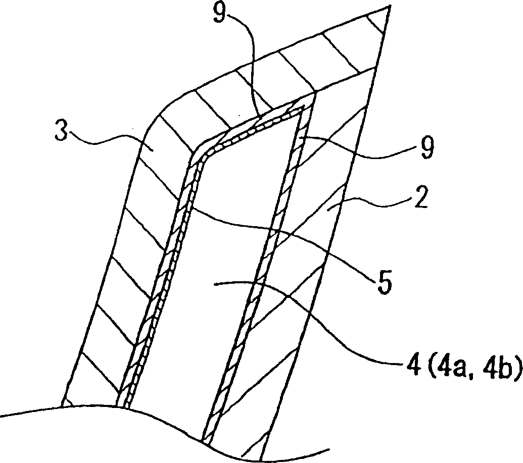
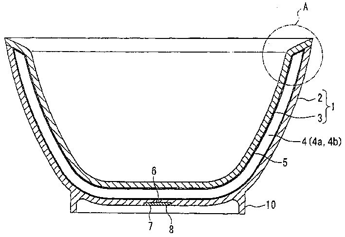
[0041] figure 1 It is a heat-insulating container made of ceramics according to an embodiment of the present invention. The heat-insulated container 1 has a structure in which an outer container 2 made of ceramics and an inner container 3 made of ceramics are integrated with a gap 4 interposed therebetween. On the outside of the inner container 3 and the inner surface of the outer container 2, such as figure 2 As shown, there is a vitreous layer 9 formed by melting and fixing the glaze. Further, on the vitreous layer 9 of the inner container 3, a radiant heat preventing film layer 5 formed of a metal film is provided. Also, at the bottom of the outer container 2, an annular foot 10 for stably placing the heat-insulating container 1 is provided, and a sealing portion is arranged in the annular center of the foot 10 to include a recess 8 and an opening 6 that runs through the center of the recess, and a closed Closing plate 7 of recess 8 .

[0042] The gap 4 between the inne...


PUM

PropertyMeasurementUnit
thermal conductivityaaaaaaaaaa

Abstract

The invention provides a heat insulation container with excellent heat insulation performance using pottery used in general households. For this heat insulation container 1 made of the pottery, an inner container 3 made of the pottery is integrated inside an outer container 2 made of the pottery through a gap part 4. A glass layer is arranged on at least one of the gap part side of the inner and outer containers or the atmosphere side of the inner and outer containers.

Description

technical field [0001] The present invention relates to a heat-insulating container made of ceramics related to soup drinks, tea bowls, etc., with a heat-insulating space layer between the walls of the double wall structure made of ceramics. Background technique [0002] Known soup drinkers with thermal insulation function include, for example, a ceramic container with a double structure proposed in Japanese Patent Application Laid-Open No. 10-316481. The soup drinker is an outer container made of ceramics, an inner container made of ceramics is placed through a gap, and the mouth is integrated, and the gap is a heat-insulated container in a decompressed state. [0003] The method of manufacturing the heat-insulated container is as follows: Firstly, a ceramic material with a double structure in which the inner container and the outer container are in a non-adhesive state is made, and a small-diameter air outflow hole is pierced on the high platform surface of the ceramic mat...

Claims


Application Information

Patent Timeline
Patent Type & Authority Applications(China)
IPC IPC(8): A47G19/00A47J41/00A47J41/02B01D53/04B28B11/04B65D13/02B65D81/38
Inventor 松田州央大塚荣二
Owner NIPPON SANSO CORP
Why Eureka
Try Eureka