Damping tools

A cutting tool and shock absorber technology, which is applied in the direction of cutting tools used in lathes, manufacturing tools, tool holder accessories, etc., can solve the problems of reducing the rotation speed, eccentricity of the counterweight part 102, changing viscosity, etc., and achieves the improvement of suppression of high frequency The effect of vibration

Inactive Publication Date: 2003-01-15
MITSUBISHI MATERIALS CORP
View PDF3 Cites 23 Cited by
  • Summary
  • Abstract
  • Description
  • Claims
  • Application Information

AI Technical Summary

Problems solved by technology

[0008] However, the viscous fluid 103 used as the damping element of the dynamic vibration absorber has a disadvantage that its viscosity is easily changed by the influence of heat.
The heat generated during the cutting process is transferred to the viscous fluid 103, so that when the temperature of the viscous fluid 103 itself rises, the viscosity will decrease, and the attenuation effect will decrease, so high-frequency vibration cannot be suppressed.
[0009] Moreover, in order to seal this viscous fluid inside the tool body and prevent it from leaking out, a sealing structure must be provided, which must complicate the structure of the tool body 100.
[0010] Also, since the counterweight part 102 is supported by the elastic parts 101, 101, when using the tool body 100 with such a dynamic vibration absorber as a rotary cutting tool, along with the rotation of the tool body 100, the counterweight part 102 will generate Eccentricity necessitates a reduced rotational speed, which means that this structure is not suitable for rotating cutting tools

Method used


Image

  • Damping tools
  • Damping tools
  • Damping tools

Examples


Embodiment Construction

[0045] Hereinafter, embodiments of the present invention will be described in detail with reference to the drawings.

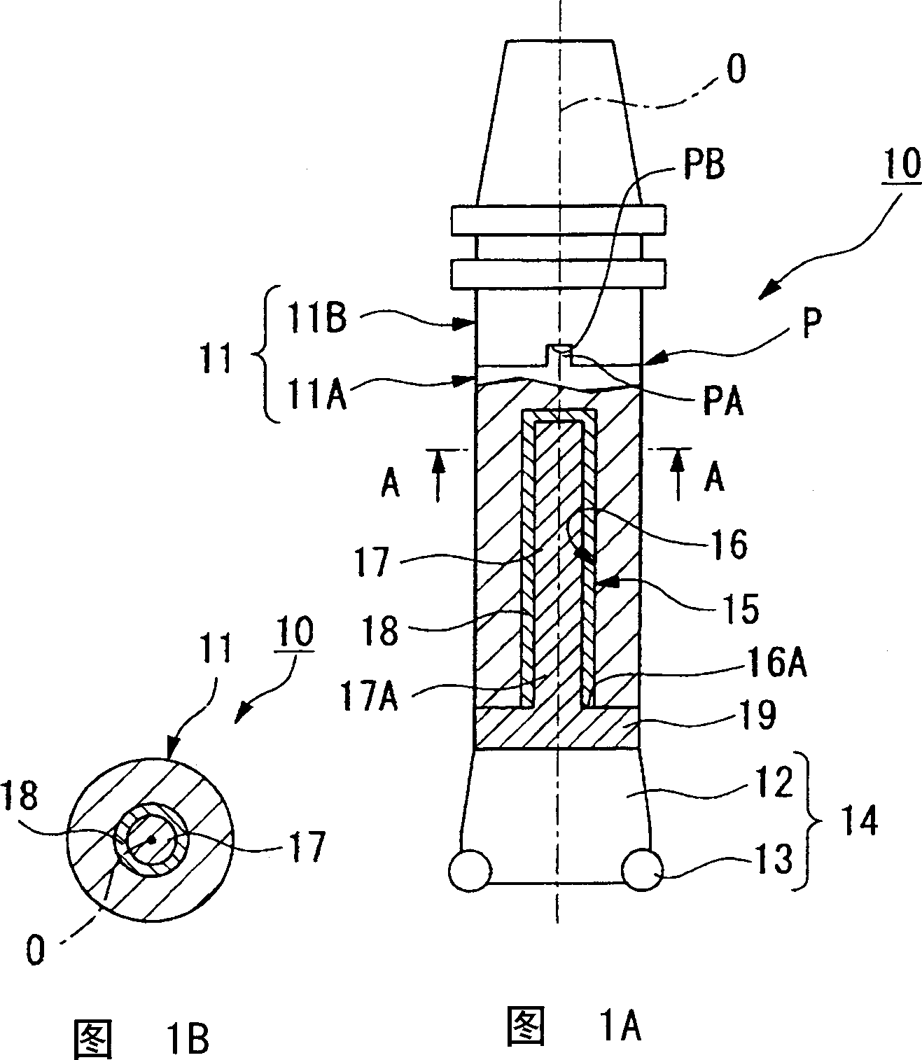
[0046] Fig. 1A is a partially cutaway side view of a vibration damping tool according to the first aspect of the present invention; Fig. 1B is a sectional view along line A-A in Fig. 1A.

[0047] As shown in FIG. 1, a vibration-damping tool 10 according to a first embodiment is a rotary cutting tool mainly formed of a tool body 11 and a head portion 14 (ie, cutting means). The body 11 is made, for example, of steel and has a bottom end supported in a cantilevered manner on the clamping portion of the machine tool. The tool body 11 is substantially cylindrical and rotates about the axis O. A plurality of throwaway blades 13 are installed on the outer circumference of the top of the head body 12 of the head 14 .

[0048] As shown in FIG. 1 , the head 14 is detachably mounted on the top end of the tool body 11 by means of fastening screws (not shown in the figu...


PUM

PropertyMeasurementUnit
elastic modulusaaaaaaaaaa
penetrationaaaaaaaaaa
tensile strengthaaaaaaaaaa

Abstract

A vibration damping tool having the following structure is provided. In the vibration damping tool, a hollow portion is formed in the interior of the distal end portion of a tool body and one end of a weight member is connected to the inner wall surface of the distal end side of this hollow portion. A gap created between the outer peripheral surface of the weight member and the inner wall surface of the hollow portion is filled with a visco-elastic body. The one end of the weight member is formed as a narrow diameter shaft portion. The tool body can be divided into two and freely removed from and reattached at a dividing surface located on the base end side of the hollow portion. A hole portion is formed inside the other end of the weight member by hollowing out the interior thereof. Chatter vibration is thus absorbed using a simple structure without there being any effects from heat generated during cutting processing.

Description

technical field [0001] The present invention relates to a vibration-damping tool capable of suppressing vibrations generated during machining of cutting materials. Background technique [0002] In the past, on the tool body such as the tool holder, the head with the throwaway insert was installed, and the tool was fed while the tool body was rotating around the axis to perform cutting of the material to be cut, or, in the The top of the tool body, such as a boring bar, is equipped with a non-regrinding insert to cut the workpiece rotating around the axis. [0003] At this time, the clamping part of the machine tool clamps the bottom end of the tool body in the form of a cantilever. When the workpiece is processed with the cutting edge of the non-regrinding blade, it will be caused by the protruding length from the clamping part to the cutting edge. And cause the natural vibration of the tool, etc., and the high-frequency vibration of resonance due to the vibration of the to...

Claims


Application Information

Patent Timeline
Patent Type & Authority Applications(China)
IPC IPC(8): B23B29/02
CPCY10T408/76Y10T82/2585Y10T409/304312B23B29/022B23B29/02
Inventor 高桥秀史石川阳一
Owner MITSUBISHI MATERIALS CORP
Why Eureka
Try Eureka