Method for producing cutter

A manufacturing method and die technology, applied in metal processing and other directions, can solve problems such as reducing manufacturing costs, and achieve the effects of reducing manufacturing die costs, saving man-hours, and saving tooling

Inactive Publication Date: 2003-01-22
王金涂
View PDF1 Cites 6 Cited by
  • Summary
  • Abstract
  • Description
  • Claims
  • Application Information

AI Technical Summary

Problems solved by technology

[0005] The present invention is to provide a method for manufacturing a knife mold, which solves the technical problems that the base and the cutter are integrally formed to achieve simple and convenient production, which is suitable for mass production and manufacturing, and further reduces the production cost; and makes the knife mold have a flexibility, The technical problem of allowing the knife mold to be bent and wrapped on the roller roller cutting machine

Method used


Image

  • Method for producing cutter
  • Method for producing cutter
  • Method for producing cutter

Examples


Embodiment Construction

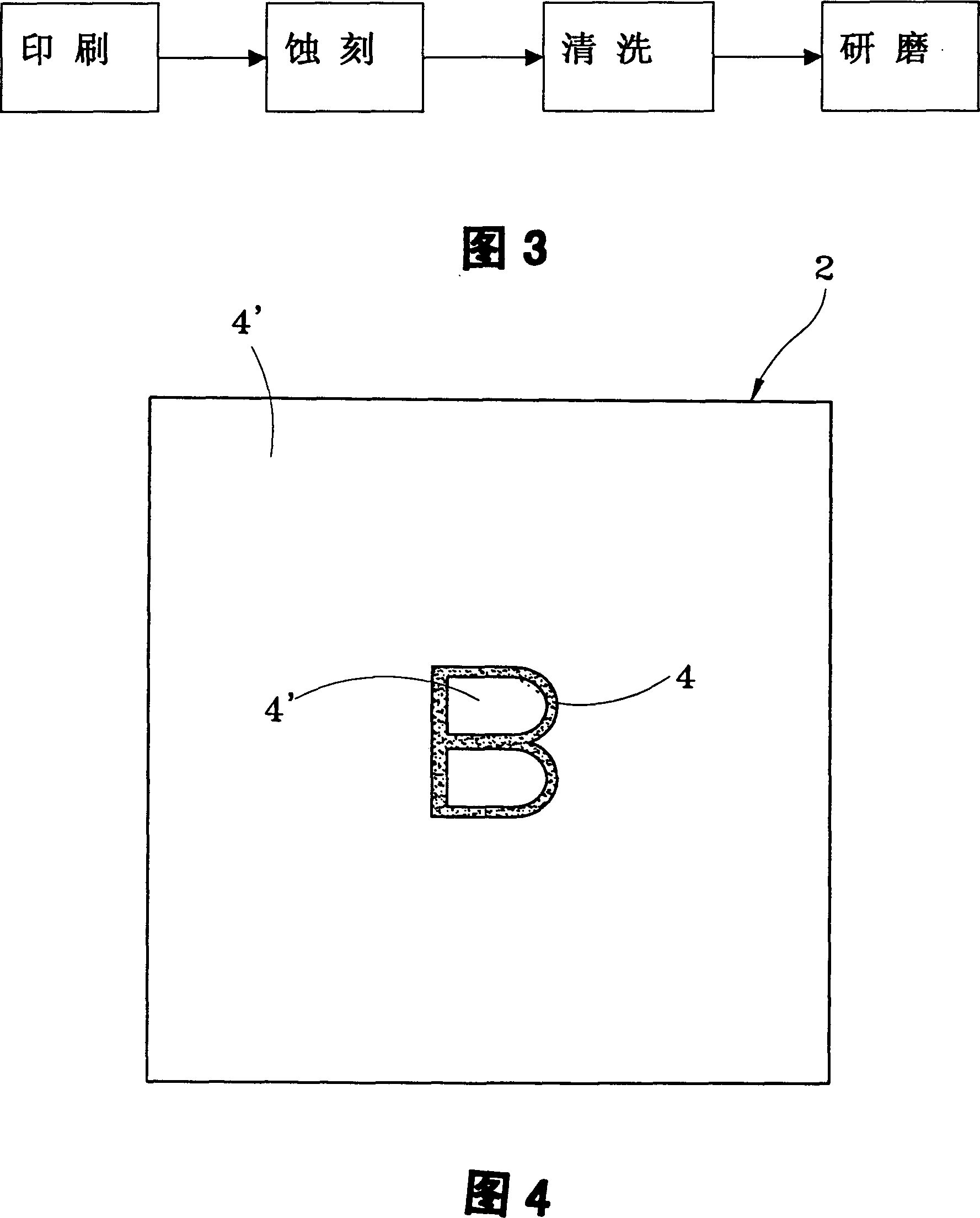
[0031] Please refer to Figure 3, Figure 4, Figure 5 , Figure 6 , Figure 7 As shown, the present invention first gets a metal plate 2 of about 1 mm when making the die 1, and prints a knife pattern formed by an ink layer 4 on the surface of the metal plate 2. After the printing process is completed, it is formed on the surface of the metal plate 2. There are two types of regions, the ink layer 4 and the ink-free layer 4'. After the ink layer 4 printed on the above-mentioned metal plate 2 is dried, carry out the etching process of the second step, and soak the metal plate 2 in a soaking container with an etching agent. The region of the ink-free layer 4 ′ on which no cutter pattern is printed on the surface is etched and sunken by the etchant. The etching speed can be adjusted by selecting and adjusting the type, concentration and temperature of the etching reagent. After the metal plate 2 etching process is completed, the metal plate 2 is immediately taken out and cleane...


PUM


Abstract

The present invention relates to the production of cutter assembled to cutting bench to cut printed matter, paper and metal board. The production process includes the step of: figure printing of the cut shape with printing ink on metal plate; etching the metal plate through soaking the plate in etching agent solution; cleaning and reaching the required itching depth; and grinding to eliminate theink layer on the metal layer and sharpening the edge of the cutter. In the present invention, cutter is formed together with its seat and this leads to simple, convenient production process suitable for mass production. The cutter has certain toughness for coating to rolling-type cutting bench.

Description

Technical field: [0001] The invention relates to a method for manufacturing a cutting knife, in particular to a method for manufacturing a knife mold assembled on a cutting machine table to cut printed articles, stickers, paper and circuit boards. Background technique: [0002] It is known that when the current cutting machine cuts the text patterns (numbers, company trademarks, labels) on printed articles and stickers, or circuit boards and papers, it uses the punch on the cutting machine to drive the die to press down. The cutting action can make the outline of the text pattern of the printed matter and stickers have cutting knife marks, and the user can tear off the text pattern according to the knife marks. [0003] And the die cutter 9 that above-mentioned cutting machine platform is used, as figure 1 , shown in Fig. 2, on this knife mold 9, have a base 91 made of wood and a cutter 92 embedded on the base 91 to form. The aforementioned method of manufacturing the die ...

Claims


Application Information

Patent Timeline
IPC IPC(8): B26D1/00B26D3/08B26F1/44C23F1/02
Inventor 王金涂
Owner 王金涂
Why Eureka
Try Eureka