
Portable electronic product outer shell and its making method

An electronic product, portable technology, applied in the casing, electrical equipment casing/cabinet/drawer, metal casing, etc., can solve problems, yield, limitations, etc.

Inactive Publication Date: 2003-03-05
HONGDA INT
View PDF0 Cites 14 Cited by
  • Summary
  • Abstract
  • Description
  • Claims
  • Application Information

AI Technical Summary

Problems solved by technology

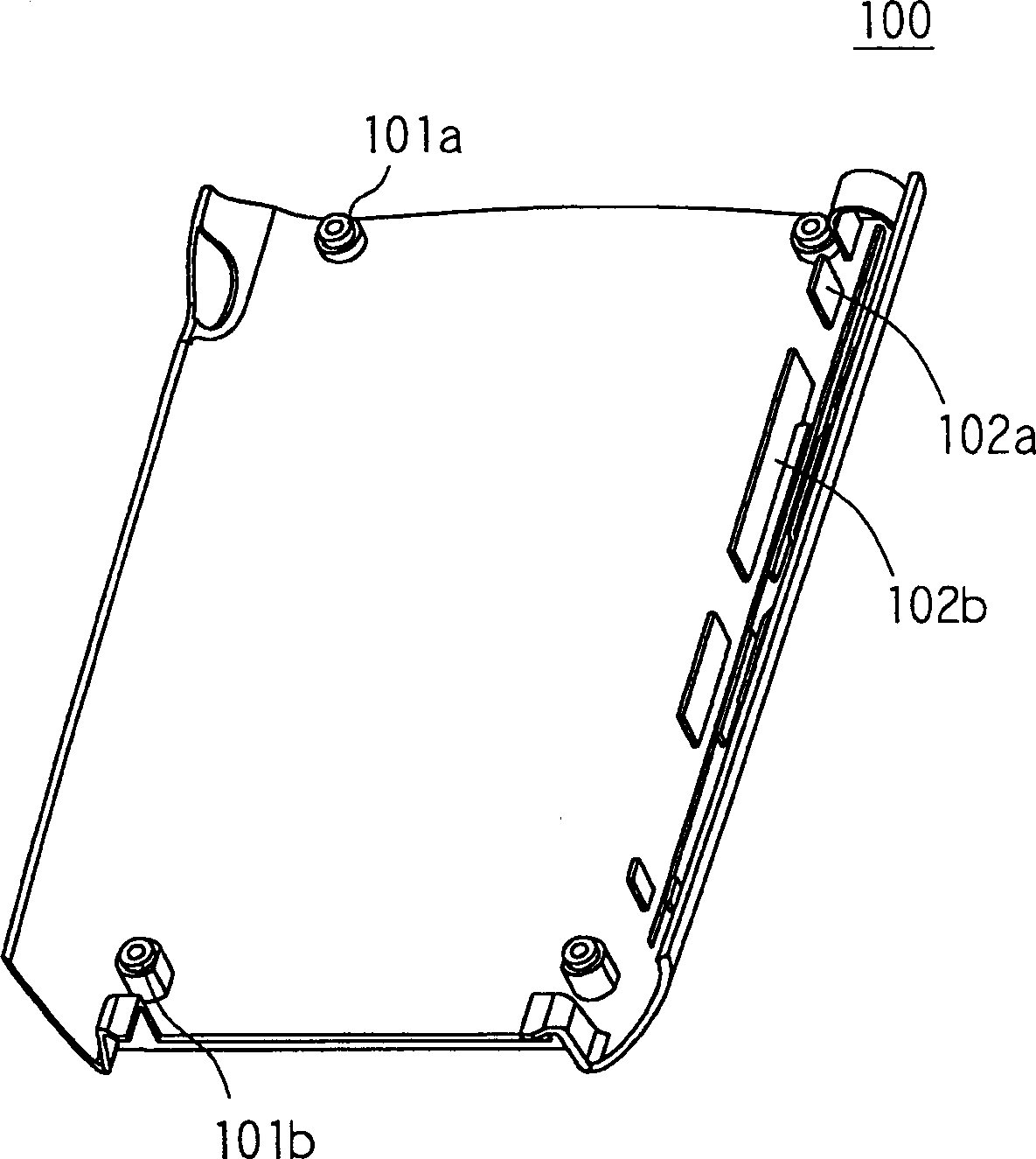
The inner side of the housing 100 is equipped with many different types of joint structures, which are used to engage with other parts of the product housing (not shown) or internal circuits (not shown). In this figure, the joint structure includes a joint 101a, 101b and plate-shaped protrusions 102a, 102b are all arranged inside the housing 100. Due to the complex structure of these combined structures, it cannot be manufactured by stamping, so currently the housing is manufactured by molding
However, the molding method still has its technical limitations. In addition to the raw material factors, the thin shell injection molding technology also needs to meet the conditions of high melt temperature, high injection pressure and high injection speed, and must also have good drainage. Gas and cooling design, based on the current technology, when using plastic as the raw material of the thin shell, it can achieve a thickness of 0.8mm ~ 0.9mm, but it may cause problems with the yield. Generally, the thickness that can be mass-produced is about 1mm about
[0006] It can be seen from the above description that in order to meet the needs of product design, molding technology is currently used to manufacture the casing of portable electronic products, and the limit is about 1mm. The existing technology has no way to reduce its thickness any further.

Method used


Image

  • Portable electronic product outer shell and its making method
  • Portable electronic product outer shell and its making method
  • Portable electronic product outer shell and its making method

Examples


Embodiment Construction

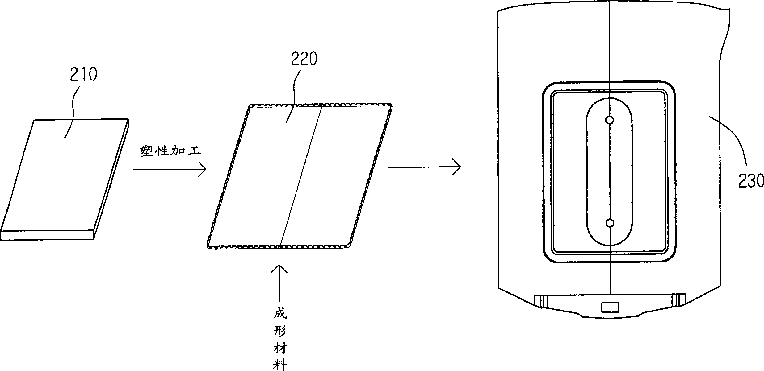
[0024] Please refer to figure 2 , which is a schematic diagram of the front-stage manufacturing process of the shell provided according to a preferred embodiment of the present invention. As shown in the figure, the metal plate 210 is processed into a metal shell 220 through a plastic processing method. The plastic processing method is selected from stamping, forging, drawing, and progressive coldforming. Generally, stamping technology is used for After the metal plate 210 is processed to make the metal shell plate 220, the metal shell plate 220 is placed in the molding mold, and then the molding material (plastic) is poured into the molding mold, and it is made by this insert molding (Insert Molding) technology. The semi-finished product 230, and then carry out surface treatment (electroplating) on ​​the semi-finished product 230, that is, this kind of shell can be made.

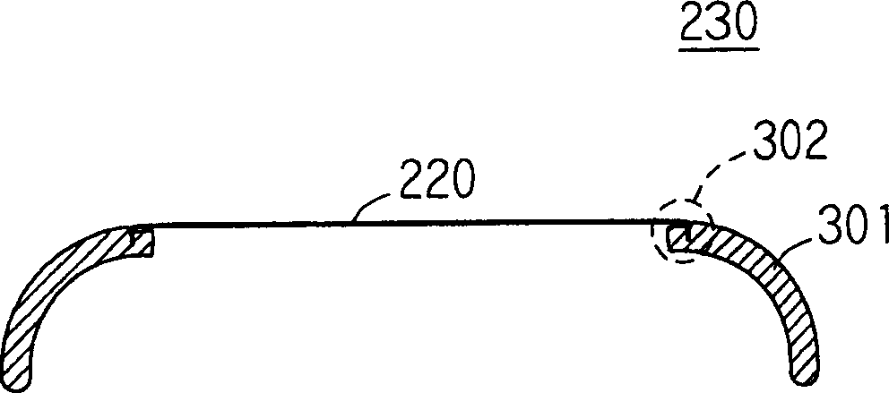
[0025] Then please refer to image 3 , what it does figure 2 Sectional view of the semi-finished pr...


PUM

PropertyMeasurementUnit
thicknessaaaaaaaaaa
thicknessaaaaaaaaaa

Abstract

A shell of a portable electronic product and its method is able to have complicated combination structure with smaller thickness containing first to produce metal plates to thin metal shell plates then to process the metal plate with a formed material to semi-manufactured goods, finally to handle surface of the semi-manufactured goods to a shell characterizing in bare surface metal shells. Apart from smaller thickness, the built-in typing technology can satisfy the dvariable change on structure.

Description

[0001] technical content [0002] The present invention relates to a casing and its preparation method, in particular to a casing manufactured by a composite manufacturing process and its preparation method. Background technique [0003] In recent years, the 3C industry occupies an extremely important position in Taiwan's electronics industry. Due to the short life cycle of the electronics industry, rapid design with light weight and finished product strength has become an inevitable trend in the new century. With the rapid development of the 3C industry, in various Products such as notebook computers, mobile phones, and Personal Digital Assistants (PDAs) will have a large market demand in the future, and will develop towards the trend of being light, thin, short, and small. The thickness reduction of the product shell can reduce the volume and weight of the product without affecting the circuit design, so it has been widely stud...

Claims


Application Information

Patent Timeline
Patent Type & Authority Applications(China)
IPC IPC(8): G12B9/02H05K5/00H05K5/04
Inventor 吴权峰
Owner HONGDA INT
Learn More