Layered decoupling coal-burning technology and mechanical layered decoupling furnace

A combustion technology and combustion furnace technology, which is applied in the field of mechanical layered decoupling combustion furnaces, can solve the problems of restricted use, increased CO and soot emissions, and increased smoke loss, so as to improve boiler combustion efficiency and reduce pollution. The effect of reducing the emission of pollutants and reducing combustion losses

Inactive Publication Date: 2003-03-19
INST OF PROCESS ENG CHINESE ACAD OF SCI
View PDF1 Cites 20 Cited by
  • Summary
  • Abstract
  • Description
  • Claims
  • Application Information

AI Technical Summary

Problems solved by technology

Due to the short residence time of the flue gas in the high-temperature area and the uneven mixing of coal combustion products and excess air, on the one hand, CO and soot cannot be burned out, and on the other hand, the NOx produced by combustion cannot be reduced, resulting in environmental pollution and low efficiency.
If the excess air coefficient or furnace temperature is increased, although the emission of CO and soot is reduced, the emission of NOx increases accordingly, and the loss of exhaust smoke increases; on the contrary, if the excess air coefficient or furnace temperature is reduced, although the emission of NOx Lower emissions, but higher CO and soot emissions
In addition, since the ignition of the coal seam starts from the upper part, some small particles of coal in the lower part will leak into the ash hopper without burning, which also reduces the combustion efficiency.
[0004] The applicant's patented technology CN 95 102081.1 in 1995 uses coal in the gasification chamber to use its own combustion heat to make coal anaerobic pyrolysis and gasification before combustion, and has successfully achieved a production rate of less than 0.5t / h. Low pollution emission of small-capacity boilers, but because the gasification chamber is mainly for anaerobic carbonization and pyrolysis of coal, the pyrolysis speed is relatively slow; the suppression of NOx emissions is mainly carried out in the semi-coke area, so the ventilation and combustion speed should not be too high quick
In addition, for the gasification chamber with a large load, there are problems such as the difficulty of coking and removing coal, which limits its application to the large-load layer combustion furnace

Method used


Image

  • Layered decoupling coal-burning technology and mechanical layered decoupling furnace
  • Layered decoupling coal-burning technology and mechanical layered decoupling furnace
  • Layered decoupling coal-burning technology and mechanical layered decoupling furnace

Examples


Embodiment 1

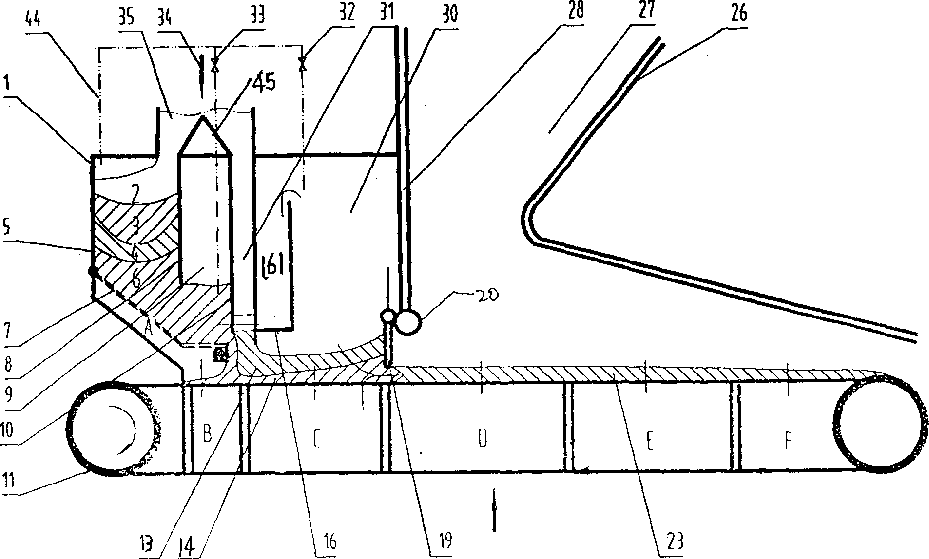
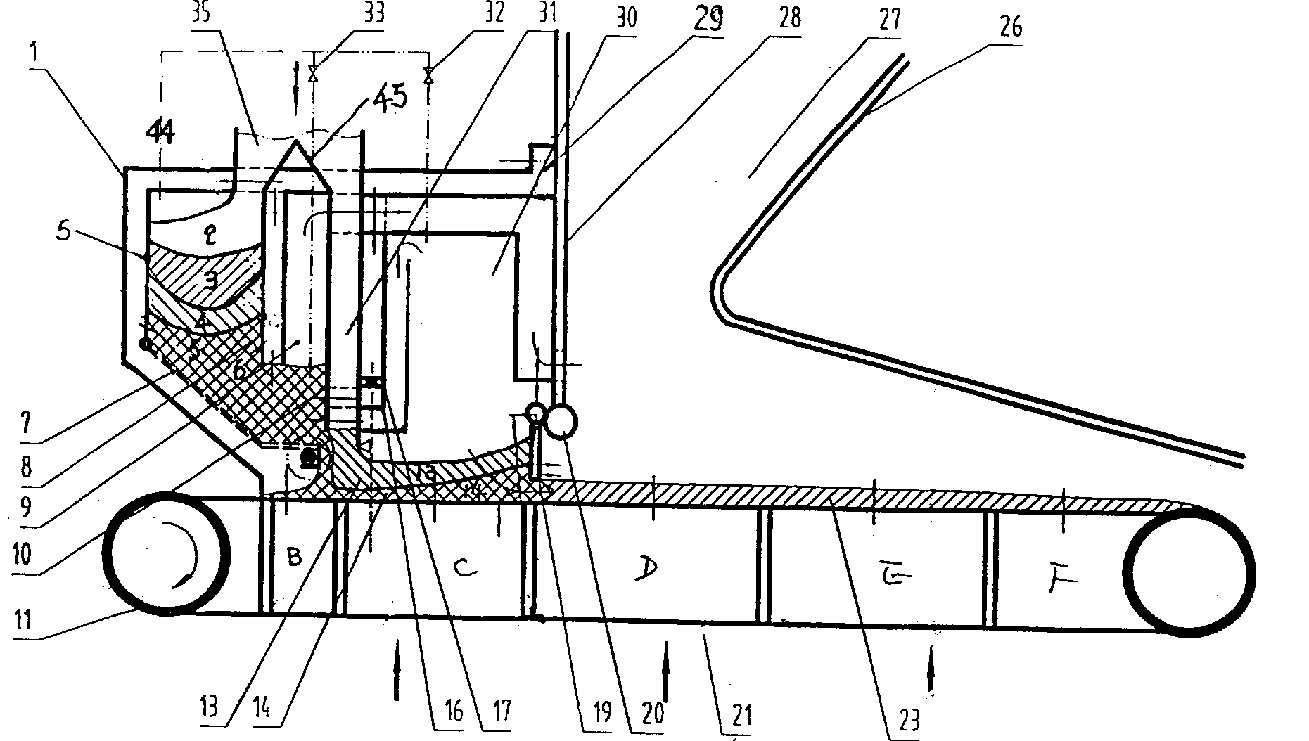
[0062] Such as figure 2 As shown, the structure of this embodiment is the same as the above-mentioned figure 1 The structure is basically the same, the differences are: the hollow air duct 36 of the middle wall 8 is provided with a baffle to adjust the air intake; the upper periphery of the pre-combustion chamber 1 and the gasification chamber 30, outside the front wall 5 and the mechanical grate 7 The bottom of each other is provided with the air supply channel 29 that is connected to each other by the air intake from the top of the gasification chamber 30 and the air supply from the bottom of the mechanical grate 7, and the rear wall air supply channel 17 is provided in the flue gas deflection channel 161, and the air supply channel 29 or an external air source supplies air to the semi-coke area 6 of the pre-chamber 1 through the rear wall air supply passage 17.

[0063] Its combustion process is:

[0064] The raw coal enters the left pre-combustion chamber 1 and the gasi...

Embodiment 2

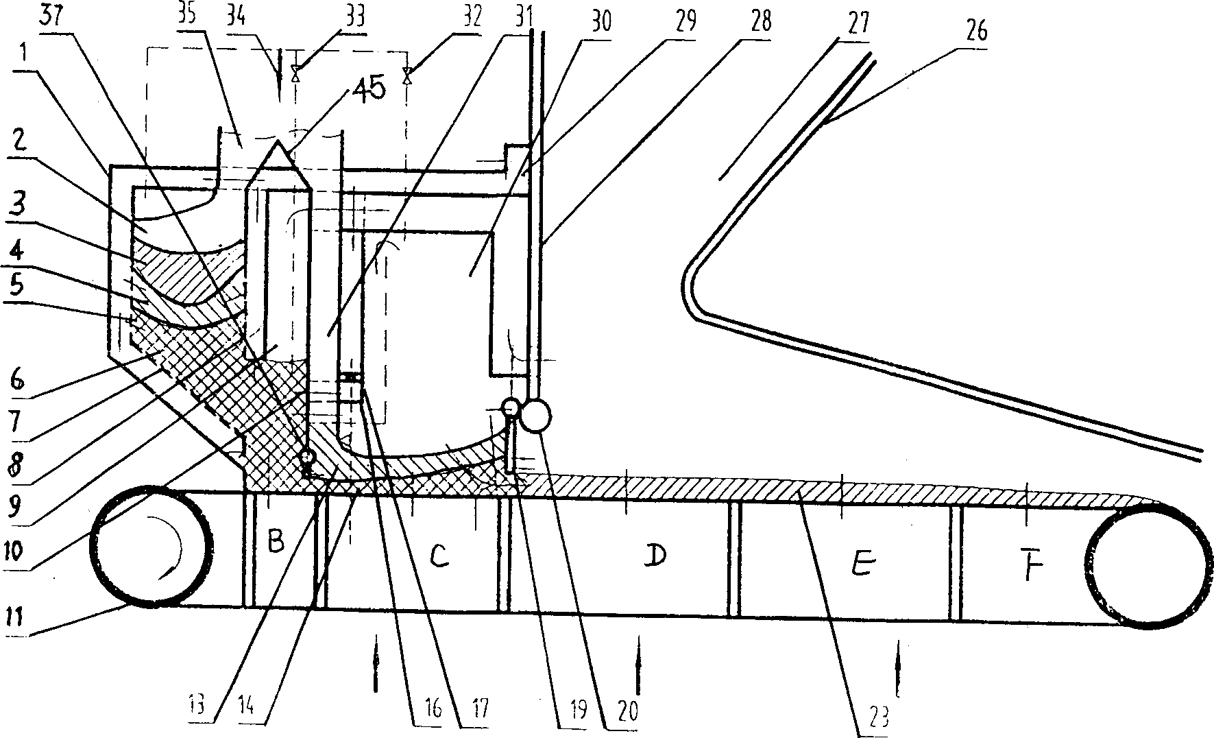
[0074] Such as image 3 as shown, image 3 The structure shown is: the mechanical grate 7 in the pre-combustion chamber 1 is a fixed grate, and the lower end of the rear wall 10 is provided with a baffle plate 37 for adjusting the amount of coke, and the rest are the same as in Embodiment 1.

[0075] There is no active grate in the pre-combustion chamber 1, and the failure rate is low, but the pre-combustion chamber does not operate independently, and the lower coke speed is controlled by the main grate 11 and the focusing amount baffle 37; The layer is very thin (30-50mm), and the coking amount baffle is easy to jam coal, so the focusing amount baffle is designed to be controlled by the heavy hammer and manual cooperation; when only the heavy hammer is controlled, the load increases, the grate speed increases, and the amount of coking Increase; the main grate load of the present embodiment is bigger.

Embodiment 3

[0077] Such as Figure 4 as shown, Figure 4 The structure: the air supply channel A communicating with it is set under the mechanical grate 7 of the pre-combustion chamber 1, and the upper part of the gasification chamber 30 is provided with an S-shaped flue gas deflector box 40, and the two outlets of the flue gas deflector box 40 communicate with the gasification chamber 30 and the flue gas baffle channel 161 respectively, and the others are the same figure 2 . The air supply to the pre-combustion chamber 1 is simplified, but the heat dissipation loss of the pre-combustion chamber 1 and the gasification chamber 30 increases, and the temperature of the primary air entering the pre-combustion chamber 1 is low, and the flue gas deflector box 40 is conducive to the mixing of the components of the flue gas , NOx reduction, and a catalyst can also be added in it under special conditions.


PUM


Abstract

The present invention relates to the layered decoupling coal buring technological and mechanical layered decoupling furnace. Coal is burned in the combustion chamber to produce fume exhausted to gasifying chamber or flue and semi-coke conveyed to the mechanical grate of gasifying chamber; the coal on the semi-coke layer is ignited from the bottom, burnt in anoxic condition and gasifying pyrolyzed; NOx in the fume is reduced into N2; and after being mixed with the second draft, CO and smoke black are burnt out. The separated burning in the mechanical layered decoupling furnace produces lowered pollutant exhaust and high burning efficiency.

Description

technical field [0001] The invention belongs to the field of raw coal combustion technology and combustion equipment, and in particular relates to a layered decoupling combustion technology and a mechanical layer that can reduce the emission of nitrogen oxides, soot and carbon monoxide from a large-load layered combustion boiler and improve the efficiency of the combustion boiler Shaped decoupled combustion furnace. Background technique [0002] At present, my country has made a lot of progress in solving the pollution discharge of small-capacity and large-capacity industrial boilers, but there are still few combustion technologies for high-efficiency and low-pollution discharge of medium-sized mechanical floor-fired boilers with large consumption. [0003] The traditional layer-fired industrial furnace has a simple structure, only figure 1 In the furnace part on the right (main combustion chamber), the coal-fired coal seam directly enters t...

Claims


Application Information

Patent Timeline
Patent Type & Authority Applications(China)
Inventor 郝江平宋文立李静海何京东朱廷玉
Owner INST OF PROCESS ENG CHINESE ACAD OF SCI
Why Eureka
Try Eureka