
Compound liquid-crystal micro-lens for sensor

A liquid crystal lens and lens technology, which is applied in the direction of lens, instrument, image data processing, etc., can solve the problems that cannot be shortened and increase production cost, etc.

Inactive Publication Date: 2003-03-26
CITIZEN ELECTRONICS CO LTD
View PDF0 Cites 12 Cited by
  • Summary
  • Abstract
  • Description
  • Claims
  • Application Information

AI Technical Summary

Problems solved by technology

[0019] (1) In order to manufacture the lenticular lens, it is necessary to provide equipment for ion conversion treatment, thereby increasing the production cost
[0020] (2) The combination distance TC between the original object and the formed image can only be selected from the lenticular lens product line
Therefore, the distance TC cannot be shortened to make a thin contact type sensor

Method used


Image

  • Compound liquid-crystal micro-lens for sensor
  • Compound liquid-crystal micro-lens for sensor
  • Compound liquid-crystal micro-lens for sensor

Examples


Embodiment Construction

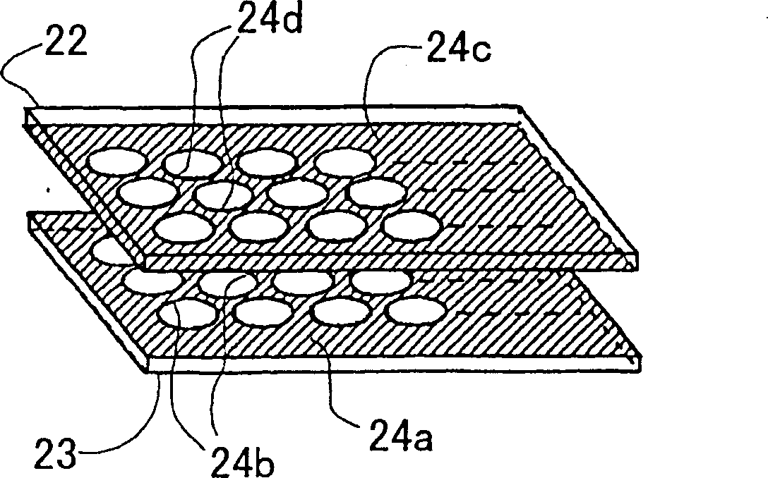
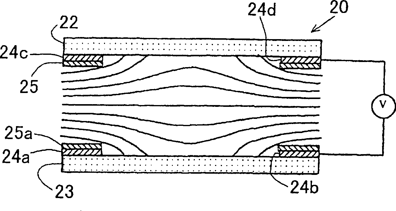
[0045] First, explain the liquid crystal lens in general. The structure and characteristics of a liquid crystal lens are described in the known publication OplusE. October 1998, Vol. 20, No. 10, Kabushiki Kaisha Shingijutsu Communication, with the characteristics of a liquid crystal optical element and its application: liquid crystal microlens. The content of the article will be described below.

[0046] In order to form an optical element used as a lens with liquid crystal, the liquid crystal layer that becomes the medium is shaped into the lens, as in a glass lens. On the other hand, an optical element can be configured so that a spatial refractive index can be imparted. In a nematic liquid crystal cell, liquid crystal molecules are aligned in the direction of an electric field. Thus, due to the symmetrical and non-uniform distribution effect of the liquid crystal molecules in the electric field about the axis, a lens with a spatial refractive index distribution can be pro...


PUM


Abstract

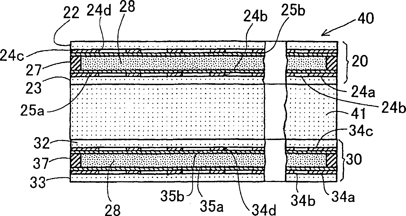
A first liquid crystal lens and a second liquid crystal lens are provided on both sides of an intermediate glass plate. The first liquid crystal lens is provided for forming an inverted image of an object, and the second liquid crystal lens is provided for inverting the inverted image, thereby forming an erecting image of the object.

Description

technical field [0001] The present invention relates to liquid crystal microlenses as means for forming images in lens arrays of contact sensors of scanners and facsimile machines. Background technique [0002] It is generally known that features such as Figure 14 and Figure 15 A contact sensor of a similar structure. [0003] refer to Figure 14 , the sensor 110 has a frame 108 in which a linear light emitting element (LED) array 105, a lenticular lens array 106 and a light receiving element array 104 are installed. The light receiving element array 104 includes a substrate 103 formed on the bottom of a frame 108, a protective film 102 mounted on the substrate 103, and a sensor integrated circuit (IC) 101 including a plurality of photoelectric converters. On top of the frame 108 is mounted a transparent plate 107, on which a text sheet 109 is mounted. [0004] In operation, a beam of light from LED array 105 illuminates text sheet 109 . Light beams scattered and refle...

Claims


Application Information

Patent Timeline
IPC IPC(8): G02F1/13G02B3/00G02B3/14G02F1/13357G02F1/1347G02F1/29G06T1/00H04N1/028
CPCG02F1/13471G02F2203/28G02B3/0056G02F1/29G02B3/0087G02B3/0062G02B3/14G02F2001/294G02F1/294
Inventor 奥脇大作佐藤進
Owner CITIZEN ELECTRONICS CO LTD
Learn More