Turbine

A technology of turbines and gas turbines, which is applied in the direction of mechanical equipment, engine components, machines/engines, etc., can solve the problems of coolant flow, difficult to realize cooling circuit, complicated sealing production, etc., and achieve high cooling effect

Inactive Publication Date: 2003-04-02
SIEMENS AG
View PDF0 Cites 5 Cited by
  • Summary
  • Abstract
  • Description
  • Claims
  • Application Information

AI Technical Summary

Problems solved by technology

This has the problem of sufficient coolant flow through the undercut
In the third variant of the seal, the cooling ducts are in the body of the block itself, which is more complicated to produce
In particular, the problem arises that in order to form the coolin

Method used


Image

  • Turbine
  • Turbine
  • Turbine

Examples


Embodiment Construction

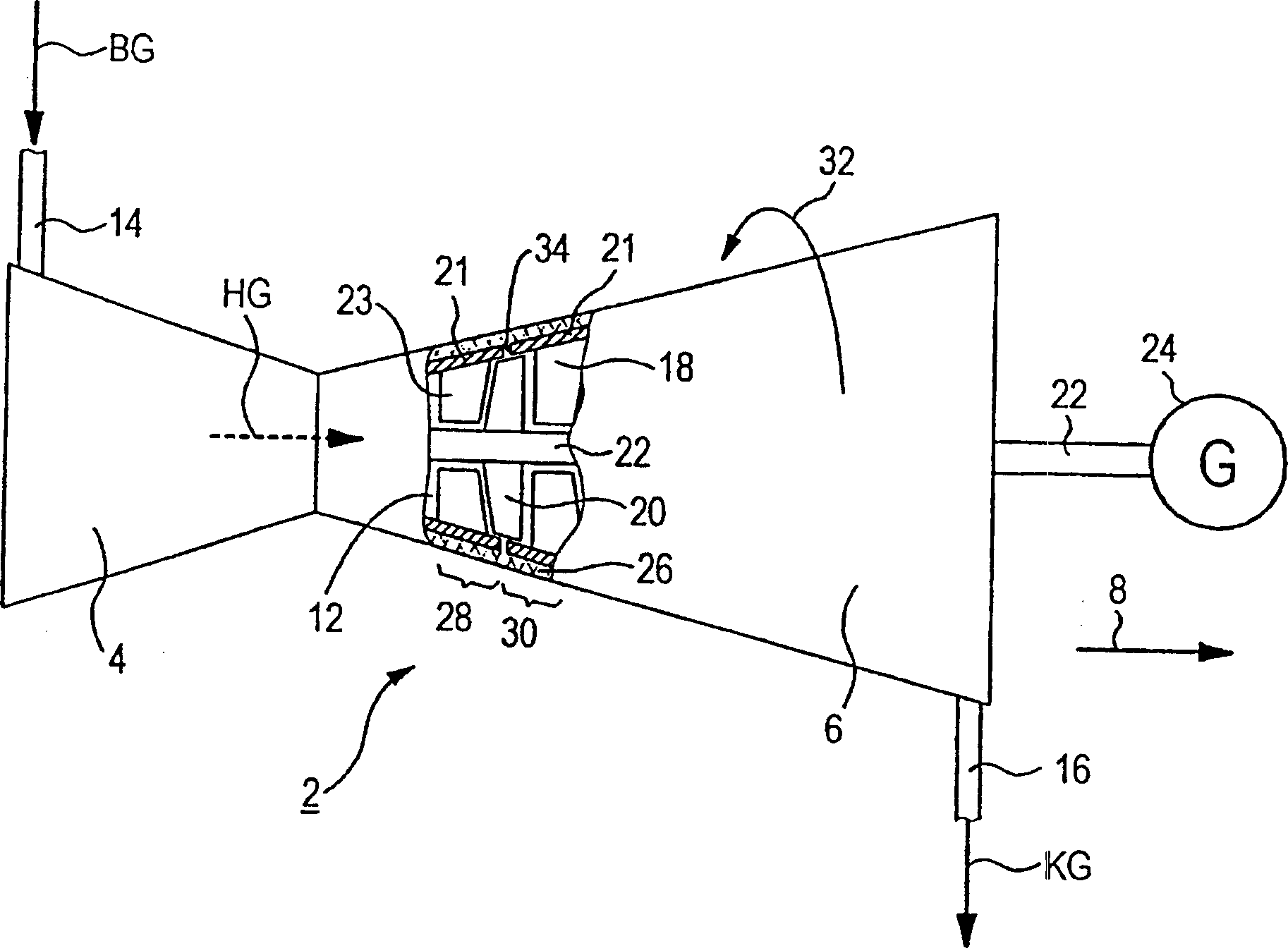
[0028] according to figure 1 , a turbine installation 2 , in particular a gas turbine installation of a turbomachine for an energy generating power plant, comprising a combustion chamber 4 and a turbine 6 arranged downstream of the combustion chamber 4 in the longitudinal or axial direction 8 of the turbine installation 2 . The turbine 6 is cut away to show a part of it, the gas space 12 of the turbine 6 can be seen. The flow path of the hot gas HG through the turbine 6 is designated as a gas space 12 .

[0029] In operation, the combustion chamber 4 is supplied via the intake pipe 14 with gas BG which burns in the combustion chamber 4 and forms said hot gas HG. The hot gas HG flows through the turbine 6 and the HG becomes cooled gas KG via the exhaust pipe 16 . The hot gas HG is guided in the turbine 6 by guide vanes 18 and moving vanes 20 . In this case, the shaft 22 on which the moving blade 20 is arranged is driven. The shaft 22 is connected to a generator 24 for gener...


PUM


Abstract

The invention relates to a turbine (6), especially a gas turbine. According to the invention, a sealing element (44) with a receiving area (50) is provided for sealing the guide blades (18) which are adjacent to each other in the peripheral direction (36) of the turbine (6). The foot plates (21) of the guide blades (18) extend into said receiving area. The edge area of the foot plates (21) does not have to be reinforced compared to a conventional seal, which enables the entire foot plate to be cooled homogeneously. A closed cooling system (62) can therefore be used for cooling, especially with steam.

Description

technical field [0001] The invention relates to a turbomachine, in particular a gas turbine. Background technique [0002] In turbines, especially in gas turbines of turbomachines in power plants that generate energy, hot gas is introduced into the turbine, with the result that a shaft on which moving blades are arranged is driven. This shaft is usually connected to a generator for energy generation. The moving blades extend radially outward. The stationary guide vanes are arranged in opposite directions, that is to say radially from the outside to the inside. As can be seen from the longitudinal direction of the turbine, the guide vanes and the moving vanes mesh with each other in a toothed manner. Turbomachines generally have a turbine stage, on which guide vane rings are arranged, ie a plurality of guide vanes are arranged adjacent to one another on the circumference of the turbine. The respective guide vane rings are arranged one after the other in the axial directio...

Claims


Application Information

Patent Timeline
IPC IPC(8): F01D5/22F01D11/00F01D25/24
CPCF01D11/005F01D5/22
Inventor 彼得·蒂曼
Owner SIEMENS AG
Why Eureka
Try Eureka