
Nuclear spin laminagraphic device through mechanical vibration to reduce vibration and noise

A tomography, nuclear spin technique used in material analysis, measurement devices, diagnosis, etc. through resonance

Inactive Publication Date: 2003-04-09
SIEMENS AG
View PDF1 Cites 13 Cited by
  • Summary
  • Abstract
  • Description
  • Claims
  • Application Information

AI Technical Summary

Problems solved by technology

[0022] Therefore, the technical problem to be solved by the present invention is to further reduce the noise transmission in the operation of the MRT device

Method used


Image

  • Nuclear spin laminagraphic device through mechanical vibration to reduce vibration and noise
  • Nuclear spin laminagraphic device through mechanical vibration to reduce vibration and noise
  • Nuclear spin laminagraphic device through mechanical vibration to reduce vibration and noise

Examples


Embodiment approach

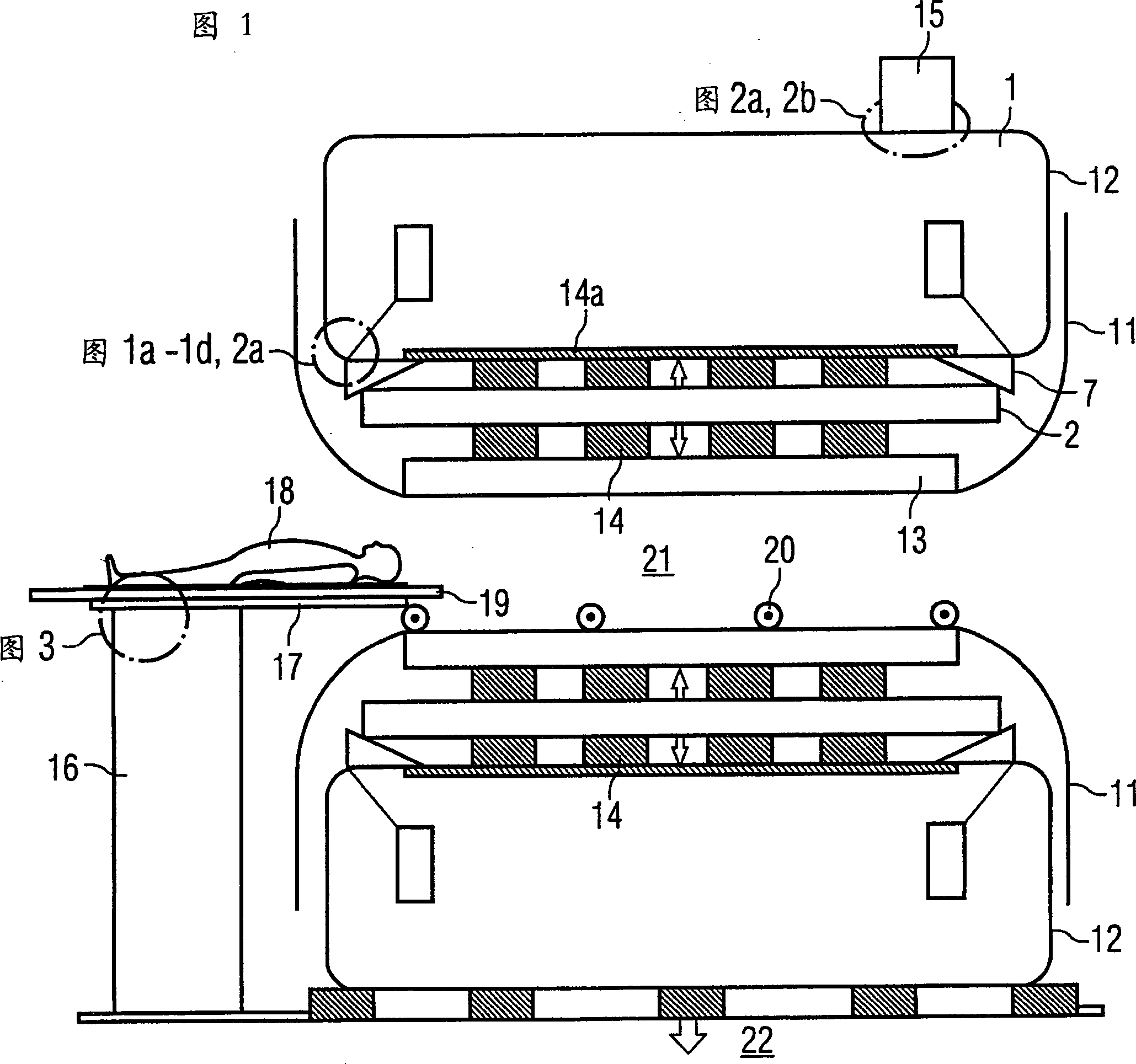
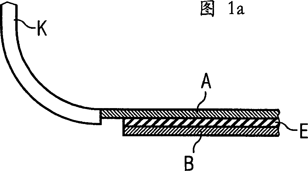
[0065] FIG. 1 a shows a system that uses a double layer structure only on the inner wall 14 a of the magnetic enclosure 12 that isolates the inner chamber 21 . The inner layer A, like the end face K, is used to form a vacuum inside the magnetic cover 12 to resist the external air pressure. This requires sufficient mechanical rigidity to be able to withstand static negative pressure loads. In the system shown in Figure 1a, only the inner wall 14a of the magnetic enclosure 12, which isolates the inner cavity 21, is provided with another shelf B, which need not be vacuum-tight. Its task is to increase the rigidity and vibration-damping properties of the inner wall 14a. But the actual damping effect comes from the damping layer, that is, the middle interlayer denoted by E between the two plates A and B. This layer is bonded to adjacent metal layers A and B.

[0066] By changing the voltage applied to the layer E, the deformation of the layer A (due to, for example, induced forc...


PUM


Abstract

In a magnetic resonance tomography MRT apparatus noise suppression by strong damping of mechanical vibrations, in particular gradient coils and magnet vessels, is achieved through the use of composite materials that have electrostrictive properties. The invention generally relates to a nuclear spin tomography method (thesaurus: magnetic resonance tomography method MRT) for the examination for patient in iatrology. The invention especially relates to a nuclear spin tomography apparatus, wherein, many kinds of vibrations of the equipment parts which cause bad effect to the whole system can be depressed, and noise transmission routes can also be reduced. The nuclear magnetic resonance tomography apparatus has a base magnet (1) covered by a magnetic housing (12) that surround an inner space (21) in which the gradient coil system (2) is arranged. The apparatus includes damping elements (14), arranged at an inner wall of the magnetic housing (12) that surround the inner space (21), for absorption of acoustic vibrations, that are produced during switching of the gradient coil system (2). The damping elements contain material with electrostrictive properties.

Description

technical field [0001] The invention relates generally to nuclear spin tomography (synonym: magnetic resonance tomography, MRT), as it is used in medicine to examine patients. In particular, the invention relates to a nuclear spin tomography apparatus in which vibrations of device components, which in many respects have a detrimental effect on the overall system, are damped. Background technique [0002] MRT is based on the physical phenomenon of nuclear spin resonance, which has been used successfully for more than 15 years as an imaging method in the fields of medicine and biophysics. In this examination method, the object is placed in a strong and constant magnetic field, which orients the spins of the otherwise randomly oriented atomic nuclei within the object. High-frequency waves excite the "ordered" nuclear spins at this time to produce certain vibrations. This vibration generates the required measurement signal within the MRT, which is picked up by a suitable recei...

Claims


Application Information

Patent Timeline
IPC IPC(8): G01R33/385G10K11/16G10K11/168
CPCG01R33/3854G10K11/16G10K11/168
Inventor 雷纳·库思
Owner SIEMENS AG
Learn More