Shortening full-length electron gun and cathod-ray tube device using it

An electron gun and cathode technology, which is applied in the direction of cathode ray tube/electron beam tube, electrode device and related components, discharge tube solid thermionic cathode, etc., can solve the problem of shortening the overall length of the cathode ray tube

Inactive Publication Date: 2003-04-30
PANASONIC CORP
View PDF1 Cites 0 Cited by
  • Summary
  • Abstract
  • Description
  • Claims
  • Application Information

AI Technical Summary

Problems solved by technology

[0008] However, the overall length from the filament support fitting 110 of the electron gun to the accelerating electrode 108 in the above-mentioned pri

Method used


Image

  • Shortening full-length electron gun and cathod-ray tube device using it
  • Shortening full-length electron gun and cathod-ray tube device using it
  • Shortening full-length electron gun and cathod-ray tube device using it

Examples


no. 1 example

[0041] [1-1] Structure of cathode ray tube device

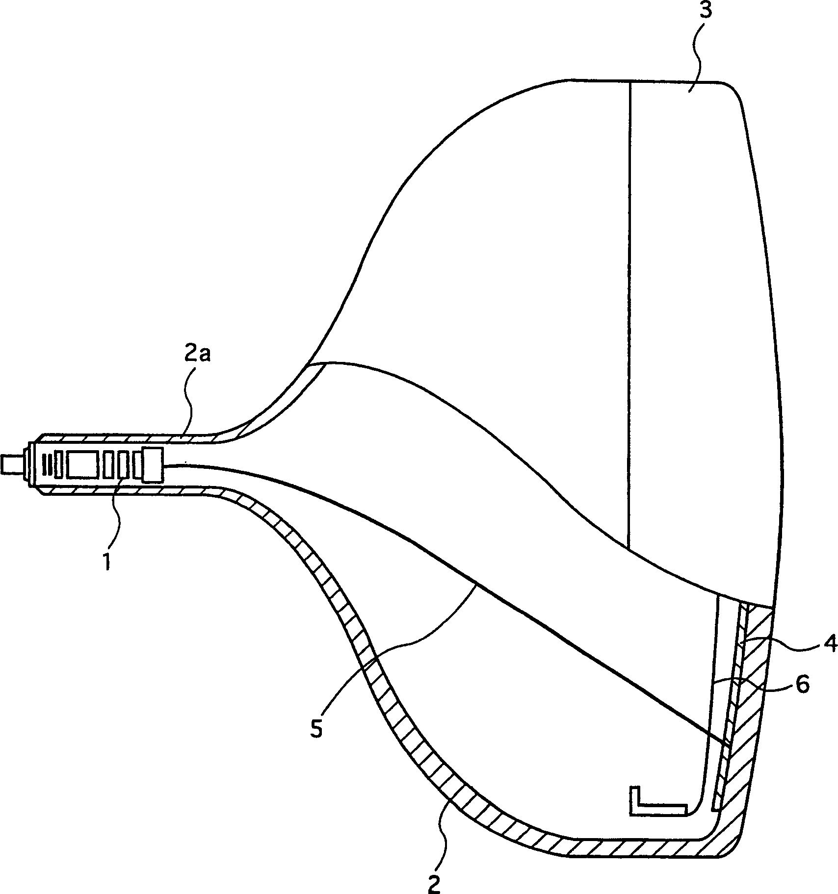
[0042] figure 2 It is a side view of the cathode ray tube device according to the first embodiment of the present invention, showing a partially cutaway cross section. like figure 2 As shown, the cathode ray tube device according to this embodiment has a peripheral frame composed of a funnel 2 and a screen 3 . The electron gun 1 is housed inside the neck 2 a of the funnel 2 . Further, blue, green, and red phosphors are coated on the inner surface of the screen 3 to form a phosphor screen 4 .

[0043] When the electron gun 1 receives an input signal, it emits electron beams 5 corresponding to the above-mentioned phosphors of each color. The electron beams 5 pass through openings formed in the shadow mask 6 to reach the fluorescent screen 4 . The phosphor screen 4 emits fluorescence when the electron beam 5 is incident to display an image.

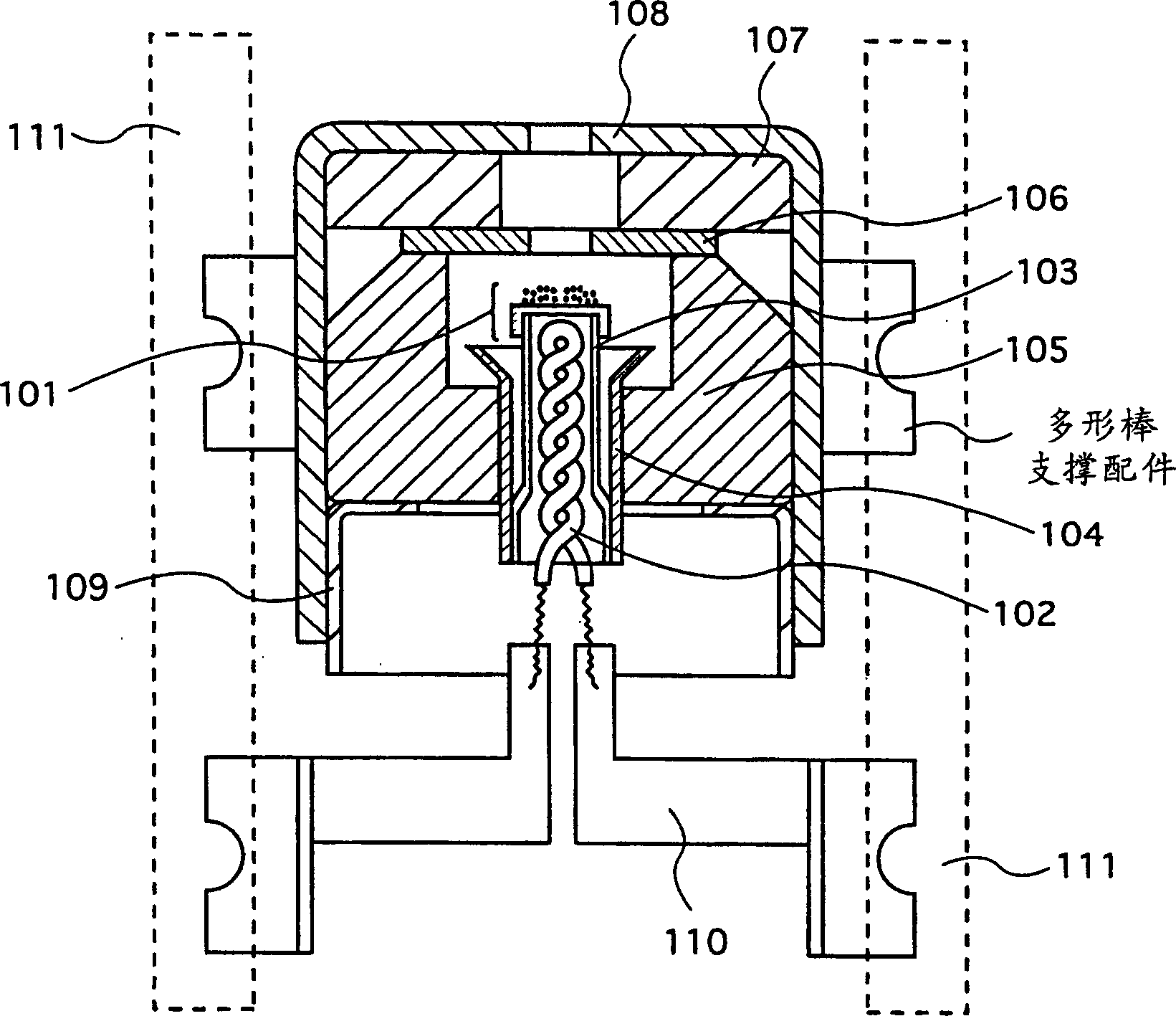
[0044] The electron gun 1 is provided with hot cathodes, accelerating electrode...

no. 3 example

[0096] A cathode ray tube device according to a third embodiment of the present invention will be described below with reference to the drawings. The cathode ray tube device according to this embodiment has substantially the same structure as the cathode ray tube device according to the above-mentioned first embodiment, and has a feature in the structure of a cathode unit integrally constituting a cathode and a control electrode. In the following, for ease of understanding, components having corresponding components in the first embodiment will be described using the same reference numerals.

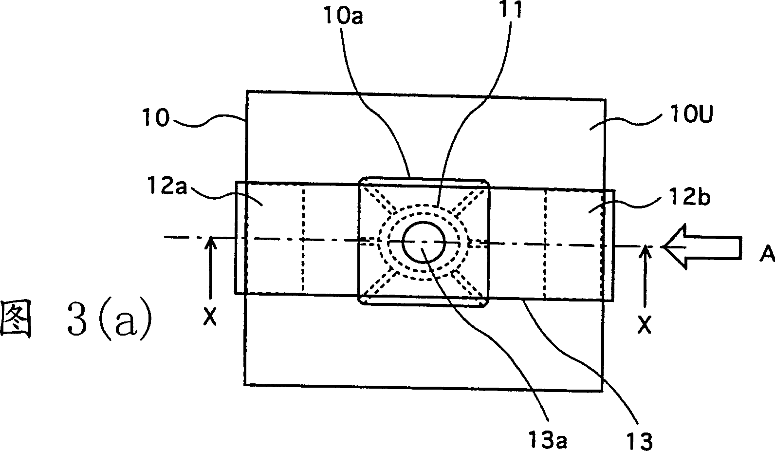
[0097] 6 is a diagram showing the structure of the electron gun of the cathode ray tube device according to the present embodiment, paying particular attention to the cathode unit. FIG. 6(a) is a view of the cathode unit viewed from the phosphor screen 4 side. FIG. 6( b ) is a view of the cathode unit viewed from the arrow A direction shown in FIG. 6( a ).

[0098] As shown in FIG. 6, ...


PUM

PropertyMeasurementUnit
Lengthaaaaaaaaaa
Diameteraaaaaaaaaa

Abstract

The present invention provides an electron gun which is characterized in that it includes an electrically non-conductive substrate through which a perforation is provided and a cathode-structure supporting member is welded to power-feeding members that are bonded to a stem side of the electrically non-conductive substrate, the cathode-structure supporting member supplying power to a heater included in a cathode structure. Structured as such, it becomes possible to reduce the size of the electron gun in the tube-axis direction, since an additional member for supporting the heater becomes unnecessary. In addition, the cathode-structure supporting member makes the electrically non-conductive substrate to work as a wiring board for supplying voltage to the cathode, thereby realizing a slim cathode-ray tube. Further, the above structure improves accuracy in the assembly process of the electron gun, thereby improving the yield factor.

Description

technical field [0001] The present invention relates to an electron gun and a cathode ray tube device, and in particular, relates to a technique for shortening the overall length of an electron gun. Background technique [0002] In recent years, flat-panel display devices such as PDP (Plasma Display Panel) and liquid crystal displays have spread remarkably. In response to this trend, the cathode ray tube device is also required to be shortened in depth. To solve this problem, an attempt has been made to shorten the overall length of the cathode ray tube device by improving the deflection yoke to increase the deflection angle of the electron beams. [0003] Furthermore, studies have been made on shortening the overall length of the cathode ray tube device by shortening the electron gun. For example, there is an electron gun structure disclosed in Japanese Patent Application Laid-Open No. Hei 2-56836. Usually, the cathode, control electrode, and accelerating electrode of an ...

Claims


Application Information

Patent Timeline
IPC IPC(8): H01J29/48H01J1/20H01J29/04
CPCH01J1/20H01J29/04H01J29/48
Inventor 山本洋二中川智山岸未果
Owner PANASONIC CORP
Why Eureka
Try Eureka