Evaporative cooling equipment of stator winding of hydraulic generator

A technology for hydroelectric generators and generator stators, which is applied in cooling/ventilation devices, electromechanical devices, electric components, etc., can solve the problems that cannot meet the cooling and safety requirements of super-large generator sets, and save investment and operating costs. The effect of simplifying operation management and improving service life

Inactive Publication Date: 2003-05-07
INST OF ELECTRICAL ENG CHINESE ACAD OF SCI
View PDF0 Cites 31 Cited by
  • Summary
  • Abstract
  • Description
  • Claims
  • Application Information

AI Technical Summary

Problems solved by technology

[0003] Obviously, the current technology of air cooling and water cooling cannot meet the cooling and safety requirements of super-large generator sets. It is necessary to research and develop new cooling media and cooling technologies to improve the reliability of safe operation.

Method used


Image

  • Evaporative cooling equipment of stator winding of hydraulic generator
  • Evaporative cooling equipment of stator winding of hydraulic generator
  • Evaporative cooling equipment of stator winding of hydraulic generator

Examples


Embodiment Construction

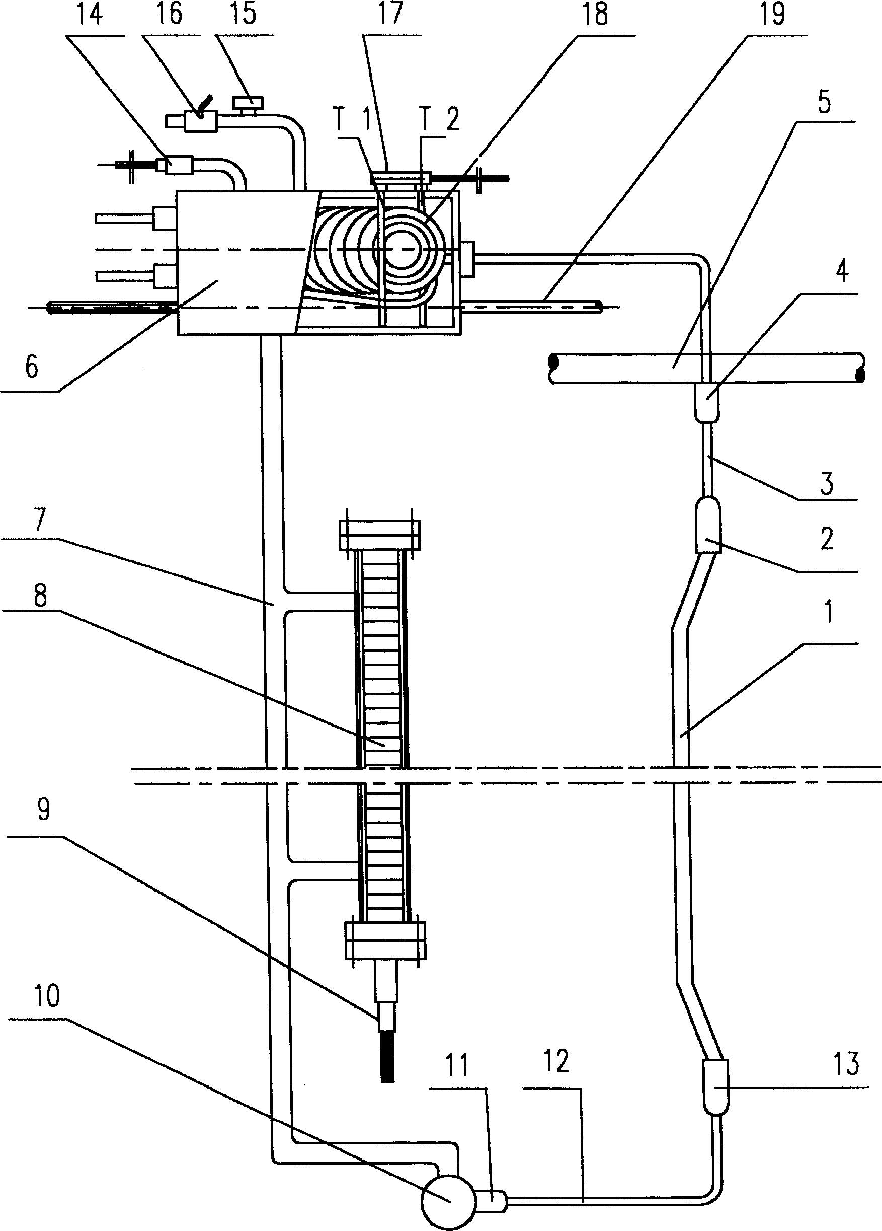
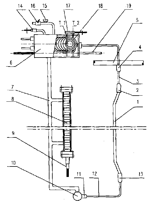
[0020] figure 1 Shown is an evaporative cooling device for the stator windings of a vertical hydroelectric generator. The stator winding 1 is composed of a hollow conductor and a solid conductor, and its upper end is connected with an upper insulating guide pipe 3 through an electro-hydraulic separation joint 2 . The electro-hydraulic separation joint is a fixed part that makes the sealing connection between the insulating lead pipe and the stator winding. The upper insulating guide pipe 3 is connected with the gas collecting pipe 5 through the sealing joint 4, and the gas collecting pipe 5 is connected with the condensing space of the condenser 6 again. The condensation space of the condenser 6 is connected with the liquid return pipe 7, and the liquid return pipe 7 is connected with the magnetic float type liquid level gauge 8 through the communication pipe. A pressure sensor 9 is installed at the lower end of the liquid level gauge. The lower end of the liquid return pip...


PUM


Abstract

The cooling system is the enclosed self-loop system with the cooling medium being filled inside. The stator winding of the generator is composed of the hollow conductor and the solid conductor combined. The upper and lower ends of the stator winding throug hthe electrolyte separation joints at the upper and lower ends are connected to the upper insulation draft tube and the lower insulation draft tube. The upper insulation draft tube through the gas collecting tube is connected to the condensation space. The lower insulation draft tube through the liquid collecting tube is connected to the lower end of the liquid returning tube. The upper end of the liquid returning tube is connected to the condensation space. The looping pipe connects multiple condensers in parallel.

Description

Technical field: [0001] The invention belongs to the cooling technology of generators, and provides an evaporative cooling device for stator windings of hydroelectric generators. Background technique [0002] As we all know, the stator windings of hydro-generators in the prior art are generally air-cooled and water-cooled. The air-cooled unit is cooled by external air blowing through winding insulation, so the cooling effect is poor, which limits the development of the unit to a larger capacity. The water-cooled unit is pressurized by the water pump to make the water flow in the hollow conductor of the winding and take away the heat, so the cooling effect is good. However, once the cooling water leaks, it often causes a short circuit, forcing the unit to be shut down for maintenance, resulting in significant economic losses. There are often reports of such accidents in the existing large-scale water-cooled generating units in the world. [0003] Obviously, the current tec...

Claims


Application Information

Patent Timeline
Patent Type & Authority Applications(China)
IPC IPC(8): H02K9/20
Inventor 顾国彪田新东熊楠国建鸿袁家毅钱光岳
Owner INST OF ELECTRICAL ENG CHINESE ACAD OF SCI
Why Eureka
Try Eureka