Compensation method of current sensor and zero-flux microcurrent sensor

A technology of micro-current sensor and current sensor, which is applied in the direction of inductors, instruments, circuits, etc., can solve the problems that cannot be provided by the original current sensor, cannot track the excitation current in real time, static compensation, etc., and achieve good anti-electromagnetic interference ability, The effect of high reliability and low temperature drift

Inactive Publication Date: 2003-05-14
GUODIAN NANJING AUTOMATION
View PDF1 Cites 27 Cited by
  • Summary
  • Abstract
  • Description
  • Claims
  • Application Information

AI Technical Summary

Problems solved by technology

(see Figure 5 ) but the above compensation current It cannot be provided by the original current sensor, it needs external injection, and it is provided by the external current source to excite the auxiliary magnetic core
Chinese patent 95201568.4 discloses a compensation structure: an auxiliary magnetic core superimposed on the main working magnetic core is set, the primary coil and the secondary coil are wound on the two superimposed magnetic cores, and an auxiliary magnetic core is wound on the working magnetic core. There is a compensation coil and a compensation resistor indirectly at both ends of the compensation coil. Although the above structure improves the measurement accuracy of the current sensor, its disadvantage is static compensation, which cannot track the change of the excitation current in real time.

Method used


Image

  • Compensation method of current sensor and zero-flux microcurrent sensor
  • Compensation method of current sensor and zero-flux microcurrent sensor
  • Compensation method of current sensor and zero-flux microcurrent sensor

Examples


Embodiment Construction

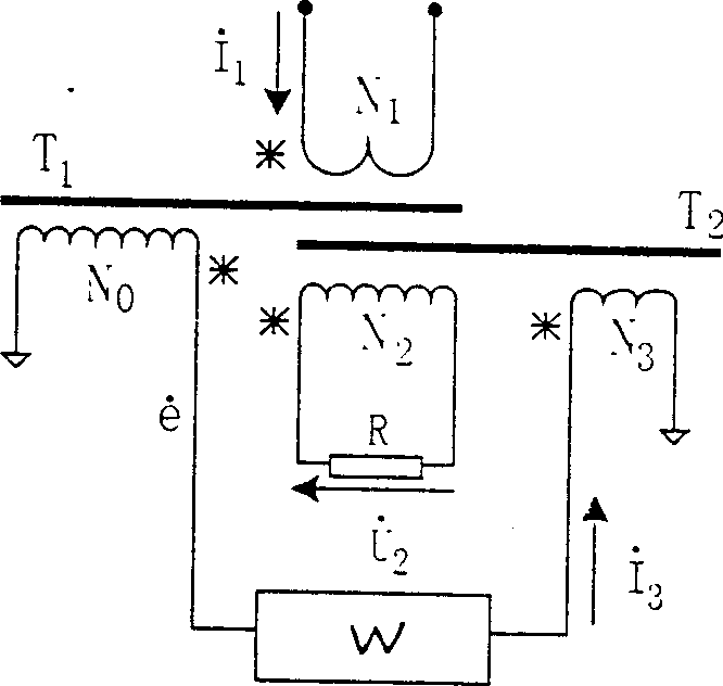
[0014] see figure 1 , the present invention adds a ring-shaped working magnetic core T on the basis of the ordinary current sensor 1 Auxiliary core T with the same shape and size 2 , the primary coil N after the two are superimposed 1 and secondary coil N 2 Wound on a laminated magnetic core, the secondary coil N 2 A load (such as a precision resistor R) is connected between the two ends of the circuit as a secondary current and then converted into a voltage signal and then amplified and output. The detection coil N 0 Wound on the working core T 1 On, compensation coil N 3 Wound on auxiliary core T 2 up, N 0 with N 3 An electronic conditioning circuit W is connected between them. Detection winding N 0 The role is to detect T 1 The magnetic density (magnetic induction intensity) in, provides the feedback voltage signal for the electronic conditioning circuit W, at N 0 There is no current in the winding, so for T 1 I will not appear when listing the balance equatio...


PUM


Abstract

A compensation method of current sensor includes real-time detection of magnetic induction density and outputting current with proper phase and magnitude via the feedback circuit for tracking compensation of the exciting current in magnetic core. A zero-flux microcurrent sensor designed based on the method has two superposed annular working magnetic cores and auxiliary magnetic core with wound primary coil, secondary coil and compensating coil as well as shielding and protecting casing outside the magnetic core. The microcurrent sensor features the primary and secondary coils on the superposed core, the secondary coil with load across it, one detection coil on the working core, a compensation coil on the auxiliary core, electronic regulating circuit comprising amplifier and voltage-to-current converter connected between the detection coil and the compensation coil.

Description

technical field [0001] The invention relates to a current sensor (transformer) for electrical measurement, in particular to a compensation method for a current sensor widely used in precision measurement in industrial field equipment and power systems, and a zero-flux micro-current designed by the method sensor. Background technique [0002] Current sensor is a widely used electrical measuring instrument. There are a large number of current sensors in industrial field equipment, primary protection and control circuits of power systems. The basic requirements for current sensors are: high accuracy, relatively flat error curve, good ability to resist external electromagnetic interference, and long-term stability. The above requirements are more important for high-precision micro-current sensors (mA level, μA level). As we all know, the current sensor realizes the energy transmission through the magnetic induction coupling between the primary coil...

Claims


Application Information

Patent Timeline
Patent Type & Authority Applications(China)
IPC IPC(8): G01R15/00H01F38/28
Inventor 徐大可曹俊岭王军锋黄建华
Owner GUODIAN NANJING AUTOMATION
Why Eureka
Try Eureka