
Crosstalk restraining method and device using optical fiber grating dispersion compensator

A technology of dispersion compensator and optical fiber grating, which is applied in electromagnetic wave transmission system, electrical components, transmission system, etc., can solve problems such as difficult to use, small residual dispersion tolerance in the range of dispersion compensation rate, etc. Simple, no insertion loss effect

Inactive Publication Date: 2011-03-30
BEIJING JIAOTONG UNIV
View PDF0 Cites 0 Cited by
  • Summary
  • Abstract
  • Description
  • Claims
  • Application Information

AI Technical Summary

Problems solved by technology

Therefore, for a system based on DCF+G.652 fiber, the requirements for suppressing its self-phase modulation and cross-phase modulation are contradictory. Therefore, its range of dispersion compensation rate and tolerance of residual dispersion are very small. It is difficult to apply it to the ultra-long-distance DWDM system

Method used


Image

  • Crosstalk restraining method and device using optical fiber grating dispersion compensator
  • Crosstalk restraining method and device using optical fiber grating dispersion compensator
  • Crosstalk restraining method and device using optical fiber grating dispersion compensator

Examples


Embodiment 1

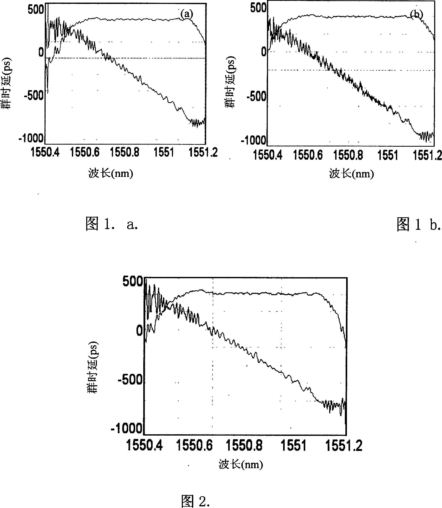
[0024] Embodiment 1: Since the written grating cannot be an ideal bandpass or bandstop, there will always be side lobes, and the reflection of the side lobes will affect the in-band flatness of other cascaded gratings. More seriously, due to The light reflected by the side lobe will fall in the band of other cascaded gratings, which is the same frequency light as the signal light of this channel, and coherence may occur, which will increase the delay ripple of other cascaded gratings, causing The waveform of the signal to be compensated is degraded, which increases the power cost of the system. No matter which fiber grating is used, this crosstalk exists.

[0025] Although the crosstalk of fiber gratings is very weak, it still has a very adverse effect on the system due to coherence. Considering that the actual use of lasers and transmitted signals in communication has a certain bandwidth, it cannot be simply regarded as monochrome. This is a partially coherent light. It is...

Embodiment 2

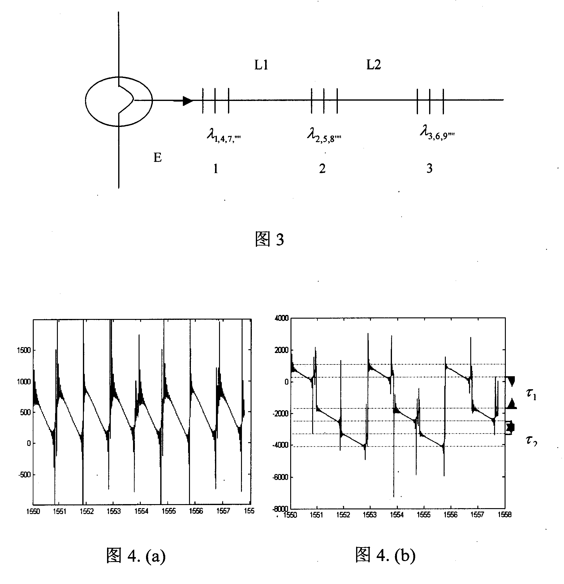
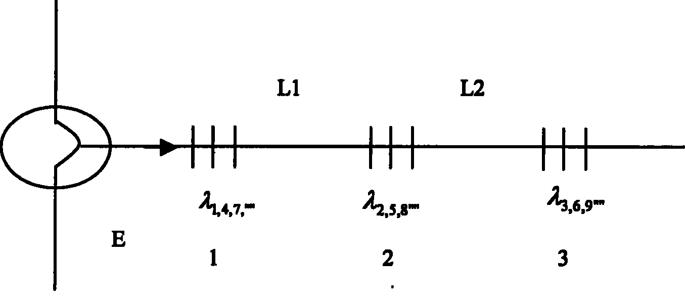
[0037] 1. Instead of using a fiber grating for dispersion compensation, the channels are grouped to minimize the interval of the same group of channels. For example, the total number of channels is N, and the channel wavelength and interval are λ 1 lambda 2 ......λ n lambda n+1 lambda n+2 ......λ N , grouping can be n, then the wavelength of each channel is; λ 1 lambda n+1 ......,λ 2 lambda n+2 ..., ..., λ n ...λ N , in fact N does not have to be a multiple of n; n is more than 1.

[0038] 2. When making fiber gratings, one fiber grating can be used for dispersion compensation for each group of channels. In this way, n channels need to use n fiber gratings (1<n<N). According to research, n does not need to be too large , generally taking n=2~4 can effectively reduce crosstalk;

[0039] 3. For a laser with a certain wavelength, its coherence length can be obtained according to the formula L=cΔt=c / Δv. When connecting fiber gratings, the optical path difference betwee...


PUM


Abstract

In WDM system, the chromatic dispersion compensation (CDC) based on multi-channel fiber raster (FR) includes wideband FR, sampling FR, super superpose FR and serial narrowband FR, etc. In all these forms, system interference includes both linear interference induced from limited extinction rate of FR and non-linear interference from cross phase modulation. This invention possesses restraint function over both linear and non-linear interference. The invention induces the cross phase modulation restrainer (CPMR) with random time-delay difference only between the neighbor channels. This chromatic dispersion compensator based on chirp fiber raster is practically an integrative scheme solving both CDC and CPMR. Its structure is simple without extra insertion loss. The system cost raises little.

Description

Technical field [0001] The invention relates to a method and device for suppressing crosstalk using a fiber grating dispersion compensator, and belongs to the technical field of optical fiber communication systems. Background technique [0002] In recent years, in the field of information technology, with the rapid development of optical fiber communication and dispersion compensation technology, the transmission rate of high-speed optical communication experimental system has reached more than tens of Gb / s, and the transmission channel has reached dozens of channels. Multi-channel dispersion compensation Technology has become a key technology to promote the development of optical fiber communication. So far, dispersion compensating fiber (DCF) has been mostly used internationally and domestically for dispersion compensation. However, DCF has a large loss and strong nonlinearity of optical fiber, which is very unfavorable for multi-channel optical fiber transmission, and it ...

Claims


Application Information

Patent Timeline
Patent Type & Authority Patents(China)
IPC IPC(8): H04B10/18H04B10/2525
Inventor 谭中伟简水生宁提钢刘艳
Owner BEIJING JIAOTONG UNIV
Learn More