
Method for all-fiber Q-switching through continuous acoustooptic diffraction

An acousto-optic diffraction, all-fiber technology, applied in optics, lasers, nonlinear optics, etc., can solve the problems of low acoustic power density, low maximum acoustic frequency, unreachable, etc. simple structure

Inactive Publication Date: 2010-08-04
UNIV OF ELECTRONICS SCI & TECH OF CHINA
View PDF0 Cites 0 Cited by
  • Summary
  • Abstract
  • Description
  • Claims
  • Application Information

AI Technical Summary

Problems solved by technology

However, the current domestic acoustic transducers have a relatively low maximum frequency of sound waves and a relatively small sound wave power density, which is far from meeting the requirements for forming leakage wave diffraction.

Method used


Image

  • Method for all-fiber Q-switching through continuous acoustooptic diffraction
  • Method for all-fiber Q-switching through continuous acoustooptic diffraction
  • Method for all-fiber Q-switching through continuous acoustooptic diffraction

Examples


Embodiment Construction

[0026] The present invention will be further described below in conjunction with accompanying drawing:

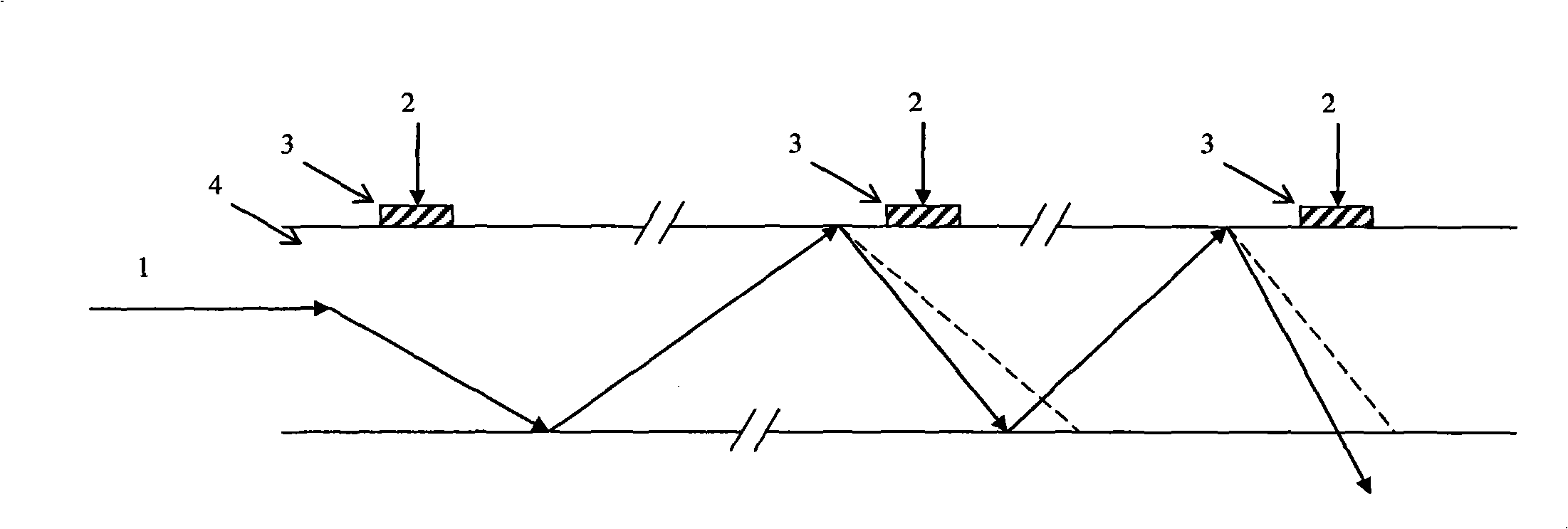
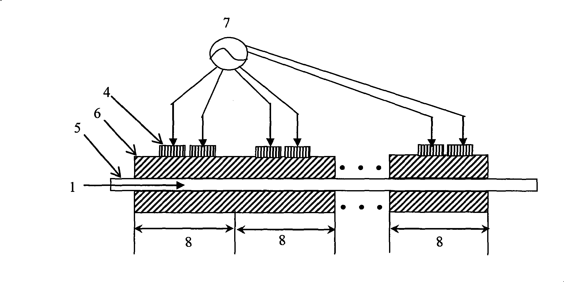
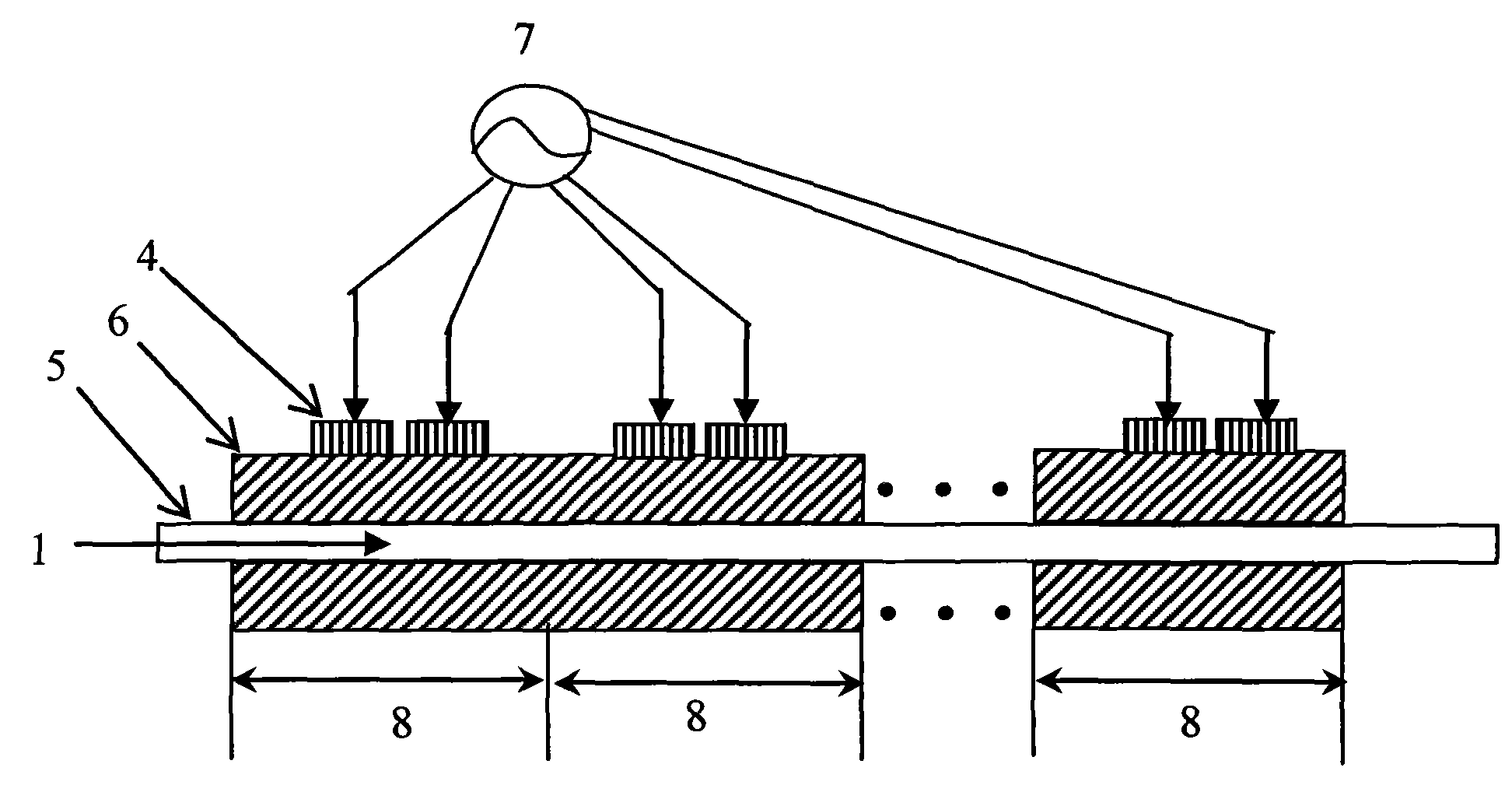
[0027] The continuous acousto-optic diffraction all-fiber Q-switching method provided by the present invention uses multiple sets of piezoelectric transducers to act on the gain fiber of the fiber laser, and each set of piezoelectric transducers has at least two piezoelectric transducers constitute. By changing the phase of the input radio frequency signal of the transducer array in each group of transducers, the output angle of the synthetic sound wave generated by the transducer array is changed to meet the requirement of the Bragg diffraction sound wave incident angle. Each set of piezoelectric transducers can generate sound wave incident angles satisfying Bragg diffraction. After multiple groups of acousto-optic Bragg diffraction, the laser in the gain fiber is separated from the limitation of the numerical aperture, thereby forming a leaky wave, increasing the loss of...


PUM


Abstract

The invention discloses a method for all-fiber Q-switching through continuous acoustooptic diffraction. A plurality of groups of piezoelectric transducers act on gain fibers of a fiber laser, the piezThe invention discloses a method for all-fiber Q-switching through continuous acoustooptic diffraction. A plurality of groups of piezoelectric transducers act on gain fibers of a fiber laser, the piezs, phase gratings in the gain fibers disappear, and the laser is in a high Q-value state. The method is used for solving the problem of adopting the lower incident sound wave frequency and the lowerars, phase gratings in the gain fibers disappear, and the laser is in a high Q-value state. The method is used for solving the problem of adopting the lower incident sound wave frequency and the lower sound wave power density to finish the Q-switching of the fiber laser.sound wave power density to finish the Q-switching of the fiber laser.oelectric transducers are connected with a plurality of paths of radio frequency signal sources, and each group of the piezoelectric transducers at least consist of two piezoelectric transducers; theoelectric transducers are connected with a plurality of paths of radio frequency signal sources, and each group of the piezoelectric transducers at least consist of two piezoelectric transducers; theemergence angle of a synthetic sound wave generated by a piezoelectric transducer array is changed by changing the phase of an input radio frequency signal of the piezoelectric transducer array in eacemergence angle of a synthetic sound wave generated by a piezoelectric transducer array is changed by changing the phase of an input radio frequency signal of the piezoelectric transducer array in each group of the piezoelectric transducers, so that the emergent angle satisfies a sound wave incident angle of Bragg diffraction; with a plurality of groups of acoustooptic Bragg diffractions, the laseh group of the piezoelectric transducers, so that the emergent angle satisfies a sound wave incident angle of Bragg diffraction; with a plurality of groups of acoustooptic Bragg diffractions, the laser light in the gain fibers breaks away from the limitation of a numerical aperture, and the Q-value of the laser is reduced; and when a sound wave field formed by the piezoelectric transducers disapper light in the gain fibers breaks away from the limitation of a numerical aperture, and the Q-value of the laser is reduced; and when a sound wave field formed by the piezoelectric transducers disappear

Description

technical field [0001] The invention relates to the fields of acousto-optic technology and laser technology, in particular to the Q-switching technology of fiber lasers. Background technique [0002] One of the Q-switching methods for fiber lasers is to follow the traditional acousto-optic Q-switch, collimate the oscillating laser in the fiber, pass it through the acousto-optic Q-switch, and then couple it back into the fiber. Therefore, the insertion loss is very large, generally greater than 2dB. This is a large power loss for high-power fiber lasers. [0003] If the gain fiber of the fiber laser is used as the acousto-optic interaction medium, and the acoustic excitation is directly applied to the gain fiber, when the incident sound wave is incident at the Bragg angle, Bragg diffraction can be formed. According to the coupled wave equation of acousto-optic interaction and the principle of parametric interaction, it can be known that if the Bragg diffraction is to be sat...

Claims


Application Information

Patent Timeline
Patent Type & Authority Patents(China)
IPC IPC(8): H01S3/11H01S3/067G02F1/11
Inventor 周鹰王亚非高椿明王占平杨立峰刘敏
Owner UNIV OF ELECTRONICS SCI & TECH OF CHINA
Learn More