Phase controlled changing double-refraction optical fibre all optical switch
A birefringent optical fiber and all-optical switch technology, applied in the optical field, can solve the problems of poor switch curve shape, insensitive switch, loss of light energy, etc., and achieve the effect of convenient control, sensitive control, and low light power reduction
- Summary
- Abstract
- Description
- Claims
- Application Information
AI Technical Summary
Problems solved by technology
Method used
Image

Examples
Embodiment Construction
[0020] The technical solutions of the present invention will be further described below in conjunction with the accompanying drawings and embodiments.
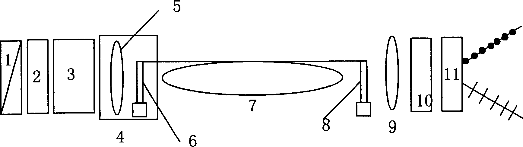
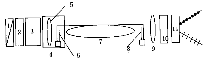
[0021] Taking the switch formed by winding low birefringence fiber as an example, the whole switch structure is as follows: figure 1 As shown, with the optical axis as the center, the polarizer 1, the quarter-wave plate 2, the half-wave plate 3, the self-focusing projection lens 5 and the fiber holder 6 included in the fiber coupling system 4 are arranged in sequence, Variable birefringence fiber 7, fiber holder 8, self-focusing lens 9, quarter wave plate 10, polarization beam splitting prism 11. The variable birefringence fiber 7 is obtained by winding a low-birefringence single-mode fiber in a plane. The main axis of the quarter wave plate 2 and the half wave plate 3 can rotate, and the variable birefringence fiber 7 is supported and fixed by the fiber holder 6 and the fiber support 8 at both ends. The main axis of the quar...
PUM
 Abstract
Description
Claims
Application Information
 - Generate Ideas
- Intellectual Property
- Life Sciences
- Materials
- Tech Scout
- Unparalleled Data Quality
- Higher Quality Content
- 60% Fewer Hallucinations
Browse by: Latest US Patents, China's latest patents, Technical Efficacy Thesaurus, Application Domain, Technology Topic, Popular Technical Reports.
© 2025 PatSnap. All rights reserved.Legal|Privacy policy|Modern Slavery Act Transparency Statement|Sitemap|About US| Contact US: help@patsnap.com