Method for igniting rotary motor without carbonbrush for driving IC engine

A technology of rotating electric machines and starting methods, which is applied to the starting of engines, the starting of motors for engines, machines/engines, etc., and can solve problems such as inability to switch to power on, accuracy rate of only 1/3, and inability to detect rotor position induced voltage, etc.

Inactive Publication Date: 2003-06-18
HONDA MOTOR CO LTD
View PDF1 Cites 4 Cited by
  • Summary
  • Abstract
  • Description
  • Claims
  • Application Information

AI Technical Summary

Problems solved by technology

In addition, in the stop positions p4 and p5, since the rotor reverses, the induced voltage necessary to detect the rotor position cannot be obtained, so it is impossible to switch to the normal

Method used


Image

  • Method for igniting rotary motor without carbonbrush for driving IC engine
  • Method for igniting rotary motor without carbonbrush for driving IC engine
  • Method for igniting rotary motor without carbonbrush for driving IC engine

Examples


Embodiment Construction

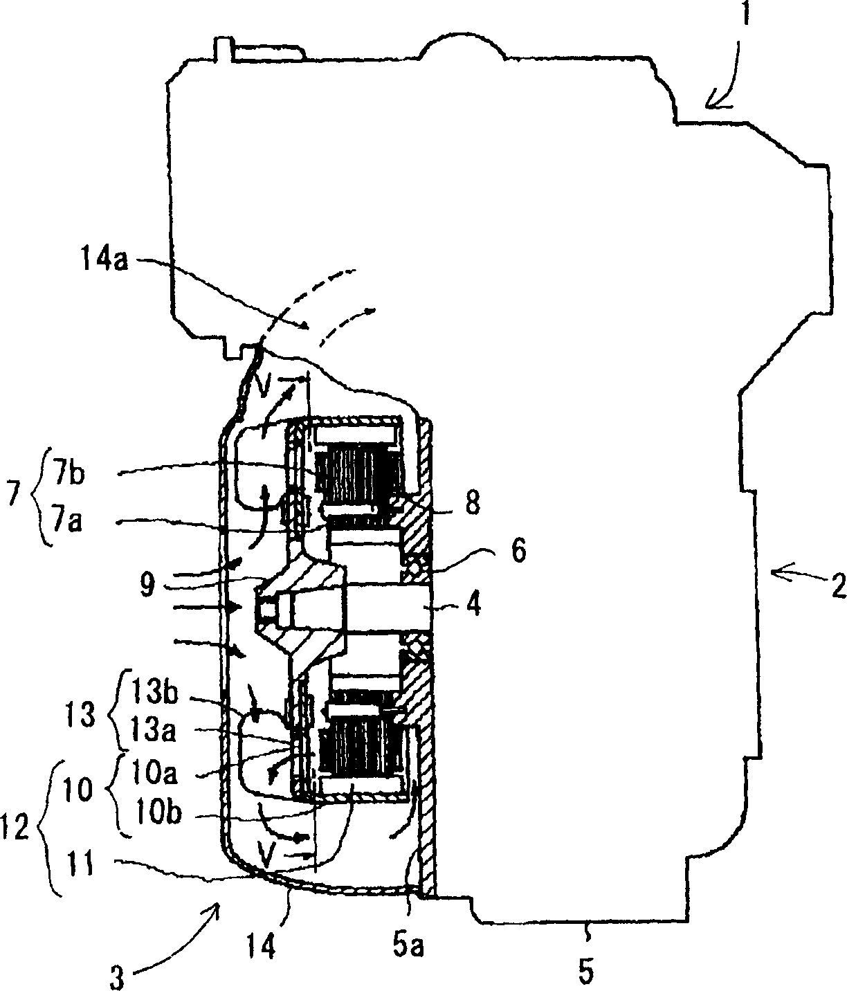
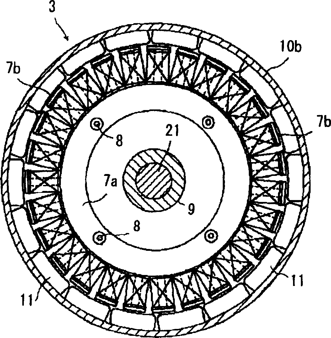
[0039] An embodiment of the present invention will be described in detail below with reference to the drawings. figure 1 is a side view of an engine power generator as an example of a brushless rotating electric machine, figure 2 yes figure 1 Sectional view of V-V.

[0040] The engine generator 1 has an engine 2 and a generator 3 . The generator 3 is a magnet type multi-pole generator. A crankshaft 4 of the engine 2 is supported by a bearing 6 provided on a side wall 5 a of the crankcase 5 . One end is drawn out to the outside of the engine 2 . On the peripheral boss of the side wall 5 a of the crankcase 5 surrounding the crankshaft 4 , an annular star core 7 is fixed by bolts 8 . The iron core 7 is composed of an annular yoke portion 7 a and 27 display electrode portions 7 b protruding radially therefrom.

[0041] Three-phase coils are alternately wound sequentially on the display pole portion 7 a to form the stator 8 . Such multi-polarization of the core 7 achieves a...


PUM


Abstract

A method of starting an electric brushless rotating machine is provided where a large startup torque is obtained with no use of any rotor position detecting device and the forced commutation can be switched to normal energization easily and smoothly. At the startup stage, any two of three-phase stator windings are energized for initial magnetization (Steps S1 and S2) to hold the magnetic rotor at a position. Then, the windings of the phases are energized in a sequence while gradually increasing the level of the energization (Step S3). During the forced commutation, the magnetic rotor is rotated by a rotating position detecting signal generated from a voltage signal induced on the not-energized windings to drive the output shaft of an engine. Then, the energization is canceled when the number of revolutions in the internal combustion engine determined from the rotating position detecting signal reaches its predetermined level.

Description

technical field [0001] The invention relates to a starting method of a brushless rotating electrical machine, in particular to a starting method suitable for a brushless rotating electrical machine which generates huge torque during starting. Background technique [0002] In a brushless motor that is a rotating electrical machine, the energization of the three-phase stator coils is performed, and the rotor (hereinafter referred to as the rotor) is sequentially switched at every 120° electrical angle to rotate the rotor. Position detection elements such as a Hall element for detecting the rotational position of a rotor included in conventional brushless motors are common. In recent years, brushless motors that do not use position detection elements have been proposed in response to the miniaturization of brushless motors. [0003] For example, in the brushless motor described in Japanese Patent Publication No. 5-24760, according to the energization between the two phases in ...

Claims


Application Information

Patent Timeline
IPC IPC(8): H02P6/08
CPCH02P6/20H02P2209/09Y10S388/912
Inventor 稲川敏规饭嵨良洋中村满脇谷勉
Owner HONDA MOTOR CO LTD
Why Eureka
Try Eureka