Fuel supply limiter for carburetor

A fuel supply and limiting device technology, which is applied to carburetors, idle speed devices, charging systems, etc., can solve problems such as difficulty in ensuring fuel tightness, fuel leakage, and troublesome assembly, achieve good space utilization, and improve fuel efficiency. Consumption and excellent responsiveness

Inactive Publication Date: 2003-07-02
HONDA MOTOR CO LTD
View PDF2 Cites 0 Cited by
  • Summary
  • Abstract
  • Description
  • Claims
  • Application Information

AI Technical Summary

Problems solved by technology

[0018] It is difficult to ensure the tightness of the fuel by installing an electromagnetic on-off valve in the fuel passage to directly limit the fuel supply (Japanese Patent No. 2860084). Fuel leakage may occur due to the use of the on-off valve in a wet environment.
[0019] In addition, in Figure 7 In the case of the example shown (Japanese Unexamined Patent Publication No. 59-229040), the piping is numerous and complicated, assembling is troublesome, and space utilization is not good.
[0020] In addition, due to the length and volume of the piping that introduces the negative pressure, the pressure fluctuation of the float chamber 04 is delayed, and the response of fuel supply restriction and release is sluggish.

Method used


Image

  • Fuel supply limiter for carburetor
  • Fuel supply limiter for carburetor
  • Fuel supply limiter for carburetor

Examples


Embodiment Construction

[0038] Below, refer to Figure 1 to Figure 6 An example of the present invention will be described.

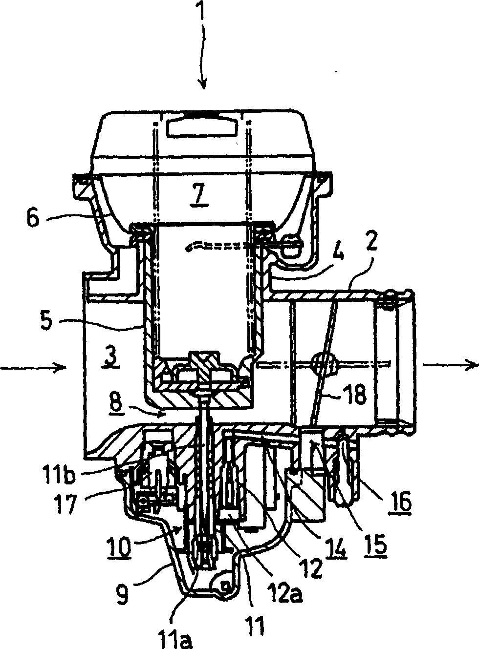
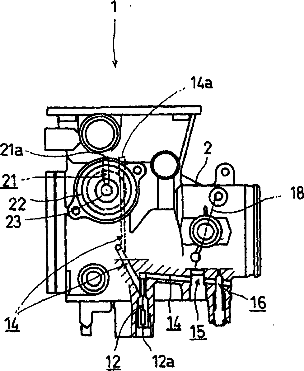
[0039] figure 1 A sectional view showing the carburetor of this embodiment, figure 2 Shows a side view in partial section.

[0040] The carburetor body case 2 of the carburetor 1 is mainly composed of a main air passage 3 and a cylindrical portion 4 slidably fitted with a piston valve 5 in a direction perpendicular to the main air passage 3 . A piston negative pressure chamber 7 is provided above the diaphragm 6 supporting the upper part of the piston valve 5 fitted in the cylindrical part 4, and a venturi part 8 is formed between the bottom wall of the piston valve 5 and the main air passage 3 .

[0041] By installing a float tank 9 under the carburetor body shell 2, a float chamber 10 temporarily holding fuel is formed below the Fenchuli 8, and a main nozzle 11 and a low-velocity nozzle 12 are arranged in the float chamber 10. The main injection hole 11a of its lower ...


PUM


Abstract

The present invention provides a fuel supply device for a carburetor that has no problem of fuel leakage and has excellent responsiveness due to simple piping. Supply mechanism, low-speed system mixed gas supply mechanism, the low-speed system mixed gas supply mechanism consists of the low-speed air passage sandwiching the low-speed air metering hole and the low-speed fuel passage sandwiching the low-speed metering hole when the throttle opening is fully closed When the opening is small, the mixed gas is supplied to the internal combustion engine, which has a second low-speed air passage (21) and a control valve (23). The upstream side of the connection point of the passage (12) communicates with the downstream side of the low-speed air volume hole (14a), and the control valve (23) is provided in the middle of the second low-speed air passage (21) for opening and closing the passage.

Description

technical field [0001] The invention relates to a fuel supply limiting device for a carburetor of an internal combustion engine. Background technique [0002] When there is a low-speed system mixed gas supply mechanism in addition to the main system mixed gas supply mechanism, when the low-load operation and no-load operation include a small opening including the throttle valve opening fully closed, the low-speed system The mixed gas supply mechanism replaces the main system mixed gas supply mechanism to supply the mixed gas to the carburetor of the internal combustion engine, in order to prevent the unburned mixed gas from being discharged into the exhaust system when the ignition circuit is opened or when decelerating, causing the catalyst of the exhaust purification device to A device for limiting fuel supply is proposed due to melting loss and the like. [0003] In addition to the example in which an electromagnetic on-off valve is interposed in the fuel passage to dire...

Claims


Application Information

Patent Timeline
Patent Type & Authority Applications(China)
IPC IPC(8): F02M3/045F02M3/09F02M3/12
CPCF02M3/09
Inventor 村冈勉安达真也
Owner HONDA MOTOR CO LTD
Why Eureka
Try Eureka