Supercharge Your Innovation With Domain-Expert AI Agents!

Devide for measuring absolute brightness of fluorescent material

A fluorescent material and absolute brightness technology, applied in the direction of fluorescence/phosphorescence, material excitation analysis, etc., can solve the problems that cannot truly reflect the luminous characteristics of the fabricated device, and achieve the effect of simple structure, convenient use, and low price

Inactive Publication Date: 2003-07-09
ZHEJIANG UNIV
View PDF0 Cites 4 Cited by
  • Summary
  • Abstract
  • Description
  • Claims
  • Application Information

AI Technical Summary

Problems solved by technology

[0003] The relative luminous brightness measured by the above method can only compare the pros and cons of the luminous properties of the two fluorescent materials, and cannot truly reflect the luminous properties of the fabricated device.

Method used


Image

  • Devide for measuring absolute brightness of fluorescent material
  • Devide for measuring absolute brightness of fluorescent material

Examples


Embodiment Construction

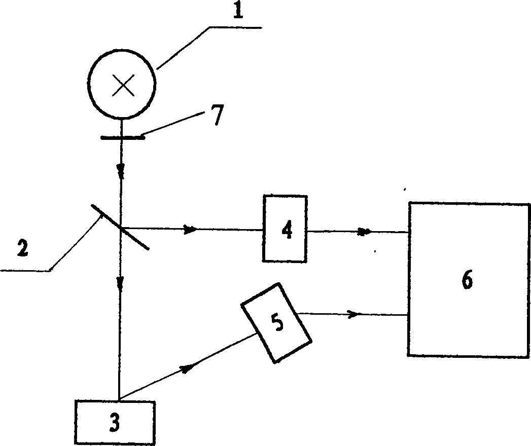
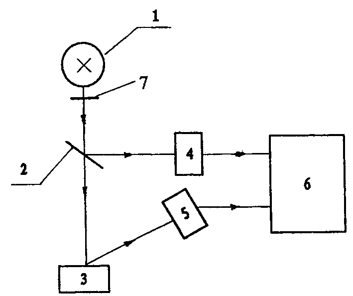
[0010] With reference to the accompanying drawings, the device for measuring the absolute brightness of fluorescent materials of the present invention includes an excitation source 1, an excitation signal sampler 2, an excitation intensity detector 4 for monitoring excitation signals, a fluorescent material sample tray 3, a brightness detector 5 and a measuring instrument 6 , in the legend, the excitation source 1 is a low-pressure ultraviolet mercury lamp, and a 253.7nm ultraviolet narrow-band filter 7 is installed in front of the lamp to cut off the remaining spectral lines of the low-pressure ultraviolet mercury lamp. The excitation signal sampler adopts a partially transparent / reflective mirror , Partially transparent / reflective mirrors can be planar quartz, magnesium fluoride or calcium fluoride. Part of the 253.7nm ultraviolet light is reflected by the partial transmission / reflection mirror 2 to the excitation intensity detector 4, and the other part of the transmitted li...


PUM


Abstract

The equipment for measuring absolute luminance of fluorescence material includes excitation source, excitation signal sampling device, excitation intensity detector for monitoring excitation signal, fluorescence material sample tray, luminance detector and measuring meter. The excitation signal produced by excitation light source can be injected into excitation signal sampling device, then the incident excitation signal can be divided into two lines, one line is reflected to the excitation intensity detector, the light signal can be converted into electric signal and transferred into measuring meter, and another line is irradiated onto fluorescence material sample tray, the fluorescence sent out by said fluorescence material can be received by luminance detector, after said fluorescence is photoelectrically converted into luminance signal, and said signal can be inputted into measuring meter.

Description

technical field [0001] The invention relates to a device for measuring the luminance of fluorescent materials. Background technique [0002] The luminance of fluorescent materials is one of the most important parameters of fluorescent materials. Traditional methods often only measure the relative luminance of fluorescent materials. The luminous intensity signals of the standard fluorescent material and the tested fluorescent material are measured by a photoelectric measuring instrument, and the reading values ​​of the two are compared to obtain the relative luminous brightness. Such as YG-II type, PR-300 type, PR-302 type and other fluorescent material relative luminance meters all adopt the above method. [0003] The relative luminous brightness measured by the above method can only compare the pros and cons of the luminous properties of two fluorescent materials, and cannot truly reflect the luminous properties of the fabricated device. For e...

Claims


Application Information

Patent Timeline
Patent Type & Authority Applications(China)
IPC IPC(8): G01N21/64
Inventor 牟同升
Owner ZHEJIANG UNIV
Features
  • R&D
  • Intellectual Property
  • Life Sciences
  • Materials
  • Tech Scout
  • Unparalleled Data Quality
  • Higher Quality Content
  • 60% Fewer Hallucinations
Learn More