Multimode optical fiber row and prism coupled double wrapping optical fiber device and its coupling method

A double-clad fiber and fiber coupler technology, applied in the field of lasers, can solve the problems of difficult realization, complex process and high technical requirements, and achieve the effect of easy simultaneous multi-point pumping

Inactive Publication Date: 2003-07-16
NANKAI UNIV
View PDF0 Cites 9 Cited by
  • Summary
  • Abstract
  • Description
  • Claims
  • Application Information

AI Technical Summary

Problems solved by technology

However, there are deficiencies. Firstly, the technical requirements for opening a V-shaped groove in the inner cladding are high and the process is complicated; secondly, the multi-V-shaped groove pump used for high-power pumping has a complex structure and is not easy to realize.

Method used


Image

  • Multimode optical fiber row and prism coupled double wrapping optical fiber device and its coupling method
  • Multimode optical fiber row and prism coupled double wrapping optical fiber device and its coupling method
  • Multimode optical fiber row and prism coupled double wrapping optical fiber device and its coupling method

Examples


Embodiment Construction

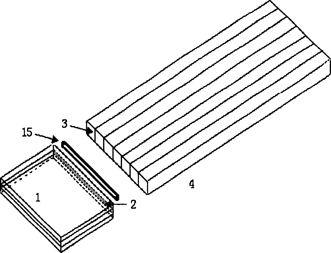
[0018] Multimode fiber row mode: figure 1 It is a schematic diagram of the optical path of the multimode fiber row coupling mode. The width of the multimode fiber row 4 is slightly larger than the width of the strip pump light output by the semiconductor laser array. The strip-shaped pumping light output by the semiconductor laser array is converged by the micro-cylindrical lens 15 and then injected into the multimode fiber row 4. After the pumping light is introduced into the multimode fiber, the multimode fibers can be scattered or concentrated into a fiber bundle or a fiber row . The light-emitting surface of the multimode fiber is ground and forms an angle α with the axis. The angle is determined according to the refractive index of the inner cladding 5 material of the double-clad fiber, so that the pump light is emitted from the light-emitting surface of the multimode fiber and then passes through the multimode fiber. The light-emitting surface and the optical contact s...


PUM


Abstract

A multi-mode optical fibre gang is prepared from multi-mode optical fibres through close arranging, fixing, and grinding and polishing its one end to form a light-receiving surface by an angle relative to optical axis. It is optically connected with a double-cladded optical fibre. A prism waveguide coupling method is also disclosed. The light is pumped to the incident surface of prism waveguide and then coupled into said double-cladded optical fibre and in turn to said optical fibre gang.

Description

technical field [0001] The invention relates to a laser device and its coupling technology, in particular to a laser technology for coupling semiconductor laser pump light into a double-clad optical fiber to generate high power, and belongs to the field of laser technology. Background technique [0002] At present, known double-clad fiber laser pumping light coupling technologies include end-pumping, side-pumping and tapered (Taper) fiber coupling. The end-pump coupling method uses a lens to focus the pump light onto the end face of the double-clad fiber and directly couples it into the double-clad fiber. The efficiency is not high, especially when the pump light power is increased, due to the limitation of the light receiving area, the optical density at the end face of the fiber is extremely high, so it is easy to cause damage to the end face of the fiber; the Taper fiber coupling method is an improved end-pump coupling method, The coupling efficiency is higher than that ...

Claims


Application Information

Patent Timeline
Patent Type & Authority Applications(China)
IPC IPC(8): G02B6/26G02B6/42H01S3/00
Inventor 董孝义袁树忠开桂云宁鼎范万德许兆文项阳张伟刚
Owner NANKAI UNIV
Why Eureka
Try Eureka