Eureka AIR delivers breakthrough ideas for toughest innovation challenges, trusted by R&D personnel around the world.

Selective colour forming glasses lens by light absorbing material and control method thereof

An ophthalmic lens, selective technology, applied in the field of controlling low reflection and transmission color

Inactive Publication Date: 2003-09-03
HAN DOK OPTEC
View PDF0 Cites 3 Cited by
  • Summary
  • Abstract
  • Description
  • Claims
  • Application Information

AI Technical Summary

Problems solved by technology

Provide low reflective multilayer film ophthalmic lenses

Method used


Image

  • Selective colour forming glasses lens by light absorbing material and control method thereof
  • Selective colour forming glasses lens by light absorbing material and control method thereof
  • Selective colour forming glasses lens by light absorbing material and control method thereof

Examples


Embodiment 1

[0050] On the convex surface of the high refraction plastic lens with a refractive index of 1.61, a silicon dioxide series hard film with a thickness of 2 μm and a refractive index of 1.62 is coated by coating, and the above-mentioned lens substrate is placed in a vacuum chamber and decompressed with a vacuum pump. 3.0×10 -5 Torr. Then, accelerate the electron beam to carry out the paste work, and in order to improve the uniformity and physical properties of the film, ionize the oxygen gas, and irradiate the ionization energy to the substrate to carry out the paste. In this way, 1.46 low refractive index dielectric SiO is pasted on the front and back of the lens 2 and 2.06 high refractive index dielectric ZrO 2 . The order and thickness are shown in Table 2 and Table 3.

[0051] Material

SiO 2

ZrO 2

SiO 2

In 2 o 3

ZrO 2

SiO 2

Thickness

0.038

lambda 0

0.065

lambda 0

0.045

lambda 0

0....


PUM


Abstract

A method to control low reflection and transmission colour for multilayer film spectacles lens which are formed with low reflection of selectivity colour by utilizing with light absorption material sticks the electrolyte having low reflection rate and high reflection rate in cross on the plastics spectacles lens with hard film coatings and inserts the film with light adsorption properties to form the multilayer film spectacles lens with low reflection of the selectivity colour.

Description

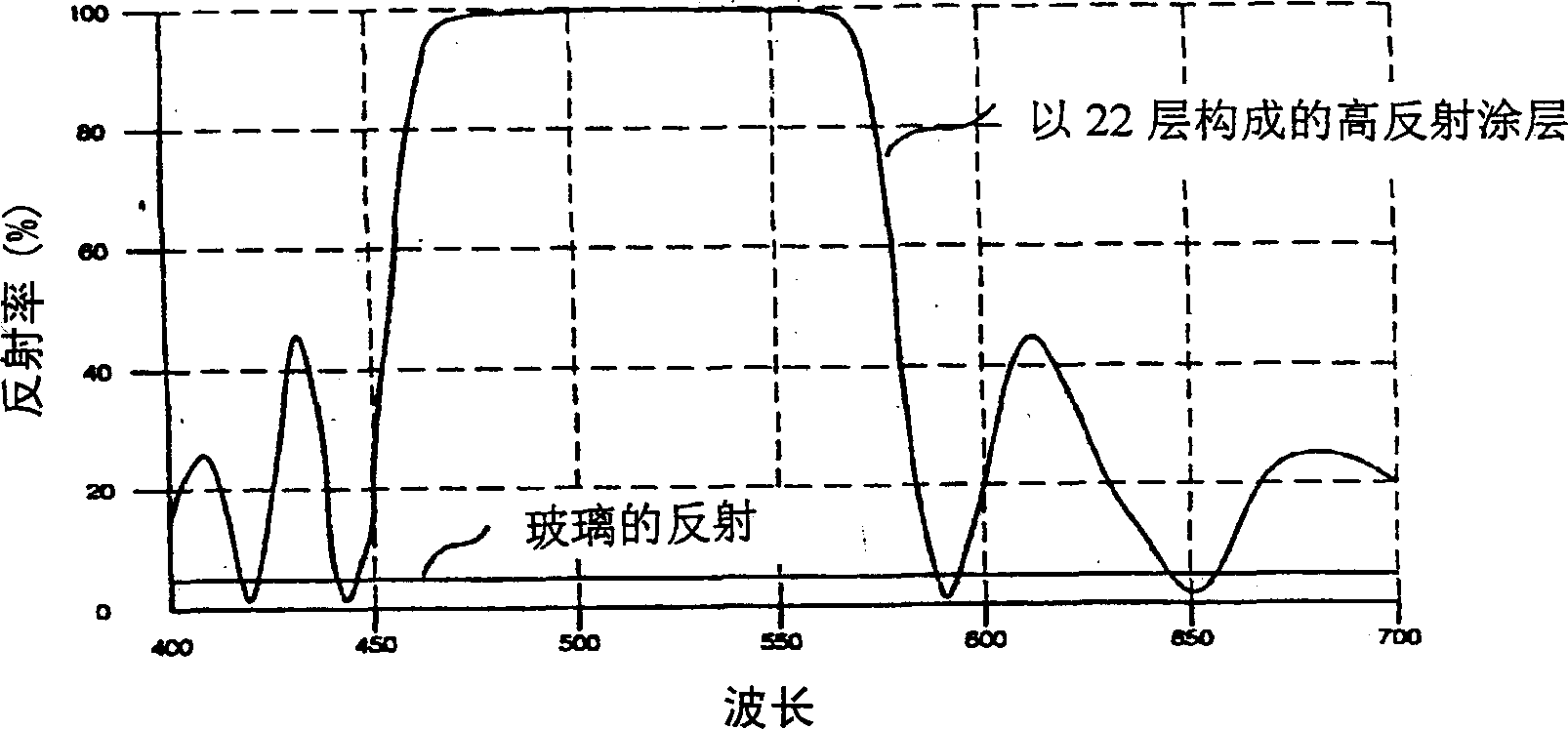
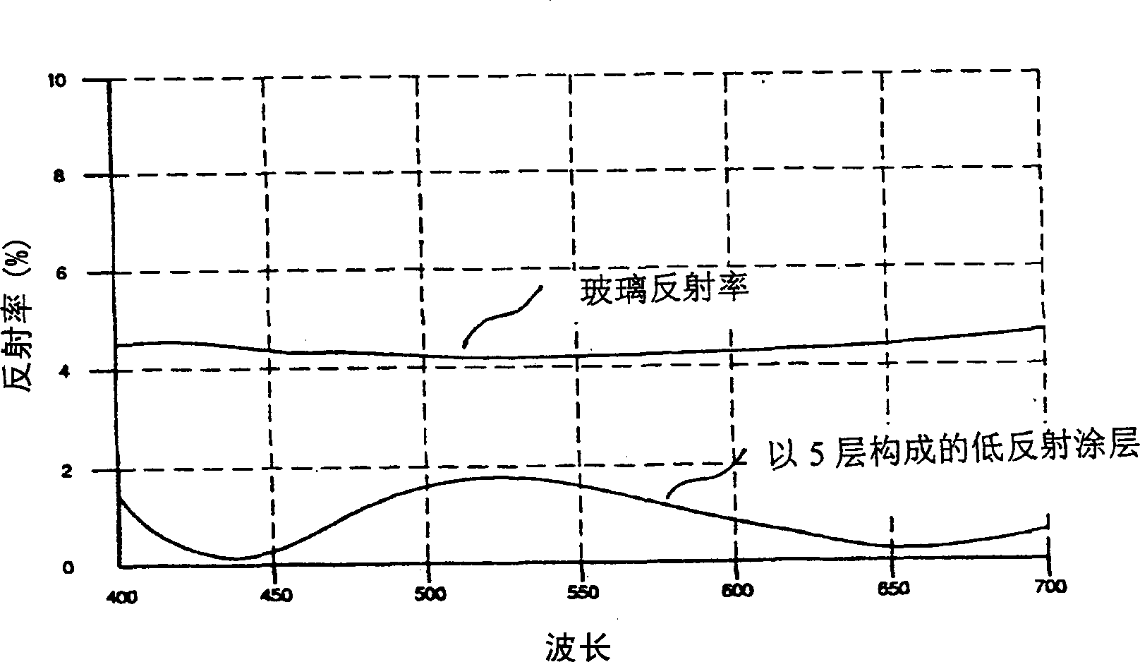
technical field [0001] The present invention relates to the use of light-absorbing substances to form selective color low-reflection multilayer film ophthalmic lenses and methods for controlling low-reflection and transmission colors. Background technique [0002] The traditional multi-layer film technology of ophthalmic lenses is to sequentially coat substances with refractive index on glass or plastic substrates, and add functions such as low reflection, high reflection or band-pass filtering. [0003] Glass sheet such as figure 1 As shown, the average reflectance is generally around 4%. Paste the low refractive index material SiO repeatedly 22 times in order 2 and high refractive index material ZrO 2 , so that it can reflect 100% in the wavelength range of 460-580nm. This paste method is called highly reflective coating. In contrast to minimizing reflectivity, the goal is to increase transmittance with reduced reflectivity. This type of paste is called a low-reflect...

Claims


Application Information

Patent Timeline
IPC IPC(8): G02C7/10
Inventor 裴在九玄盛焕
Owner HAN DOK OPTEC
Why Eureka
Eureka Blog
Learn More