Method and device for holding optical member, optical device, exposure apparatus and device manufacturing method

A technology for optical components and optical devices, which can be used in microlithography exposure equipment, optical components, semiconductor/solid-state device manufacturing, etc., and can solve the problem of high operating costs

Inactive Publication Date: 2003-09-03
NIKON CORP
View PDF5 Cites 20 Cited by
  • Summary
  • Abstract
  • Description
  • Claims
  • Application Information

AI Technical Summary

Problems solved by technology

[0020] In addition, with this method of substituting the low-absorbing gas into the projection optical system, even if the flow rate of the low-absorbing gas is not as high as that of the initial gas replacement, it is

Method used


Image

  • Method and device for holding optical member, optical device, exposure apparatus and device manufacturing method
  • Method and device for holding optical member, optical device, exposure apparatus and device manufacturing method
  • Method and device for holding optical member, optical device, exposure apparatus and device manufacturing method

Examples


no. 1 example

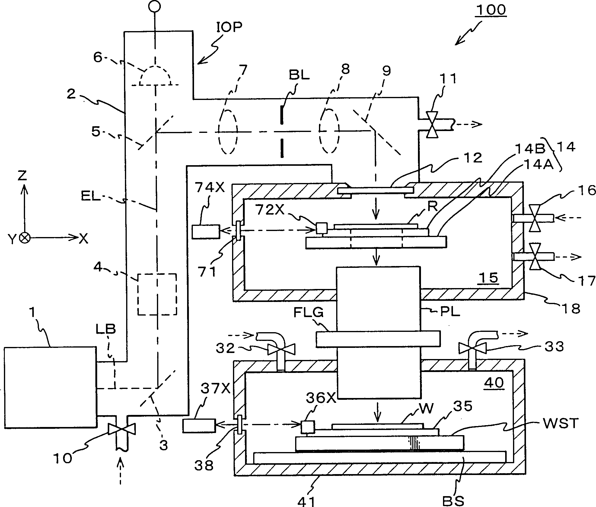
[0108] see below Figure 1~5 A first embodiment of the present invention is described. figure 1 The structure of the exposure apparatus related to the first embodiment is schematically shown. This exposure apparatus 100 is a projection exposure apparatus based on the step-and-scan method, which irradiates the reticle R with the exposure illumination light EL serving as an energy beam in the vacuum ultraviolet region, and in a predetermined scanning direction (in this case, The X-axis direction) relatively scans the reticle R and the wafer W to transfer the pattern of the reticle R as a mask to the wafer W as a substrate through the projection optical system RL.

[0109] The exposure apparatus 100 includes a light source 1 and an illumination optical system IOP. It also includes components such as an illumination system for illuminating the reticle R with exposure illumination light (hereinafter referred to as "exposure light") EL, a reticle stand 14 serving as a mask stand ...

no. 2 example

[0201] Next, referring to FIG. 6, a second embodiment of the present invention will be described. Structures and components identical or identical to those in the first embodiment are denoted by the same reference numerals and briefly described or omitted entirely.

[0202] In the second embodiment, the structure of a projection optical system serving as an optical device is different from that of the first embodiment. Other parts are the same as the first embodiment; therefore, the following description will mainly focus on this difference.

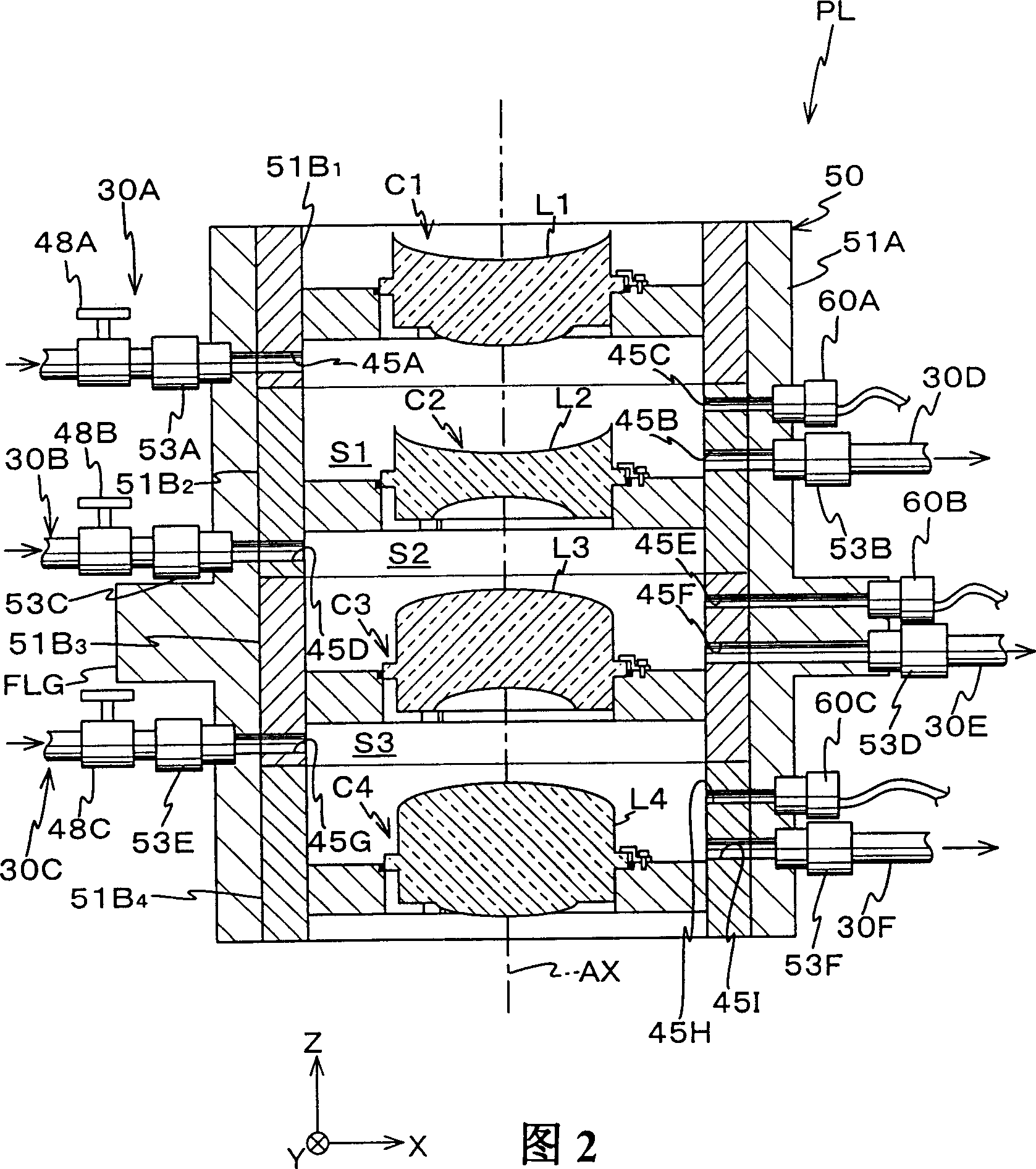
[0203] FIG. 6 shows a longitudinal cross-sectional view of projection optical system PL1 according to the second embodiment. The present projection optical system PL1 is similar to the projection optical system PL in the first embodiment, except that the pressure sensors 60A, 60B, and 60C and the airflow control valves 48A, 48B, and 48C connected to the sealed chambers S1, S2, S3, respectively, are removed, and A pair of pressure regul...

no. 4 example

[0223] A fourth embodiment of the present invention will be described below with reference to FIGS. 8 to 12 . Structures and components identical or identical to those in the first embodiment are denoted by the same reference numerals and briefly described or omitted entirely.

[0224] With the exposure apparatus related to the fourth embodiment, the structure of the projection optical system serving as the optical device is different from the aforementioned first embodiment. Other parts are the same as the first embodiment; therefore, the following description will mainly focus on this difference.

[0225] FIG. 8 shows a longitudinal sectional view of projection optical system PL3 according to the fourth embodiment, Figure 9 A cross-sectional view of projection optical system PL3 near line B-B in FIG. 8 is shown. Figure 10 also shows projection optical system PL3 along Figure 9 A cross-sectional partial end view taken along line C-C in middle, while Figure 11 Indicates...


PUM

PropertyMeasurementUnit
Thicknessaaaaaaaaaa

Abstract

A flange portion is provided to at least a part of the periphery at the center position in the direction of the optical axis of a lens. The lens is held with clamping members and a lens holding metallic part, with the flange portion pressed by the clamping members. The portion where the flange portion is provided, suffers no compressive strain and tensile strain due to the bending of the lens, and is a part of the periphery of a neutral plane, which is the farthest plane from the optical surface of the lens. Therefore, the influence of the clamping force on the flange portion acting on other portions of the lens is reduced to the utmost, and the deformation of the optical surface due to the force acting on the flange portion is reduced to a minimum. As a result, the deterioration of the optical properties of the lens can be suppressed to the utmost.

Description

technical field [0001] The present invention relates to a method and apparatus for fixing an optical element, an optical apparatus, an exposure apparatus and a method for manufacturing the apparatus, and more particularly to an optical element fixing method and apparatus for fixing an optical element such as a lens with a flange on a peripheral portion , an optical device having a plurality of optical elements in its lens barrel, an exposure apparatus including the optical apparatus as its optical system, and an apparatus manufacturing method using the exposure apparatus. technical background [0002] Conventionally, various exposure equipments are used in photolithography processes for manufacturing semiconductor devices. For example, in recent years, semiconductor devices have been produced mainly by projection exposure equipment such as reduced projection exposure equipment (so-called steppers) that pass through a projection optical system based on the step-and-repeat met...

Claims


Application Information

Patent Timeline
IPC IPC(8): G02B7/02G03F7/20
CPCG03F7/70833G02B7/022G03F7/70883G03F7/70866G03F7/70933G03F7/20
Inventor 西川仁
Owner NIKON CORP
Why Eureka
Try Eureka