
Valve less thin film driving micro pump

A film-driven, micro-pump technology, applied in pumps, machines/engines, pumps with flexible working elements, etc., can solve problems such as unstable flow, and achieve the effects of fast response, easy integration, and simple structure and process

Inactive Publication Date: 2003-09-17
HUAZHONG UNIV OF SCI & TECH
View PDF0 Cites 34 Cited by
  • Summary
  • Abstract
  • Description
  • Claims
  • Application Information

AI Technical Summary

Problems solved by technology

[0004] The purpose of the present invention is to overcome the deficiencies of the prior art and provide a valveless film-driven micropump, which is a single-membrane double-chamber structure, which can effectively solve the problems of periodic fluctuations and flow instability , so that the output flow is continuously stable

Method used


Image

  • Valve less thin film driving micro pump
  • Valve less thin film driving micro pump
  • Valve less thin film driving micro pump

Examples


Embodiment Construction

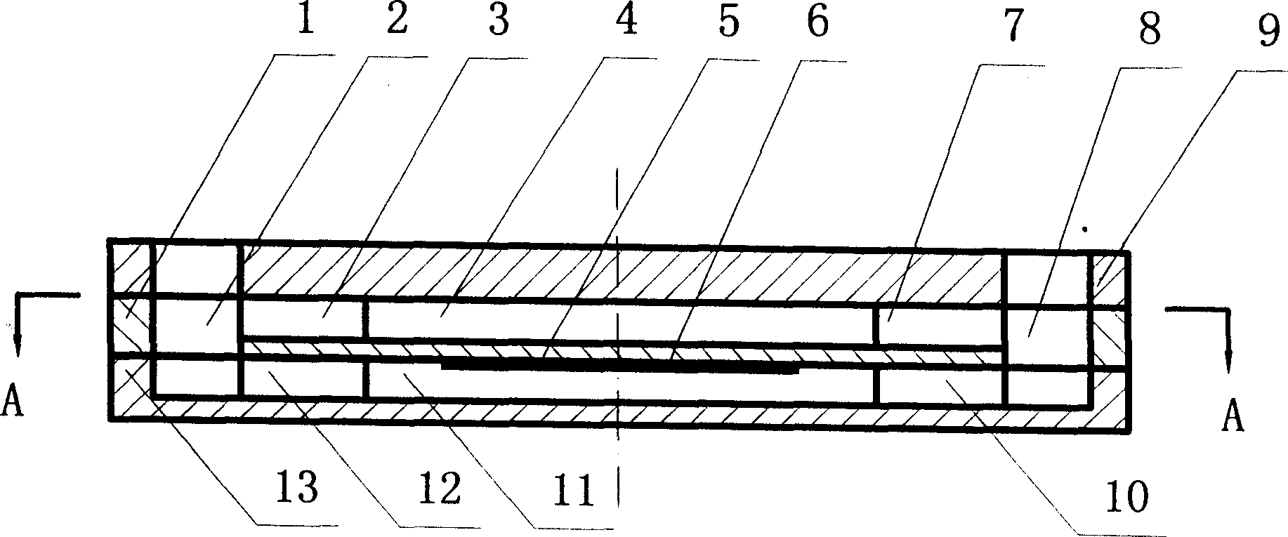
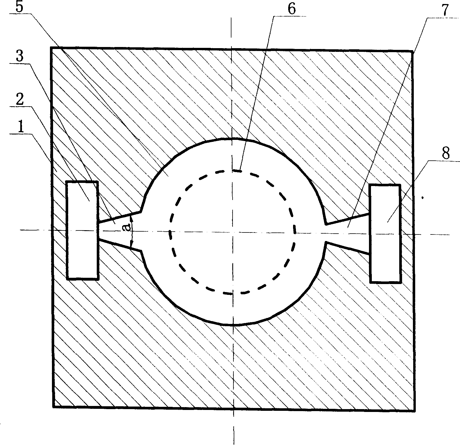
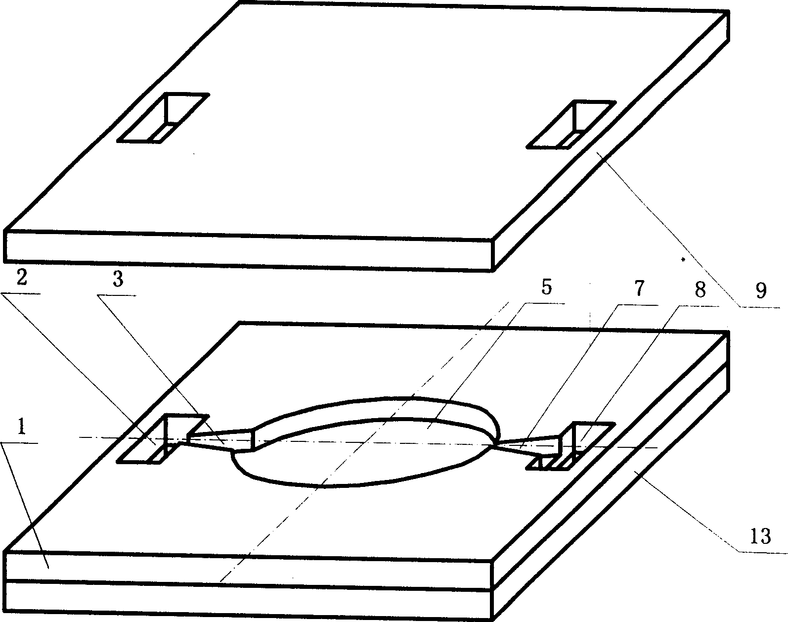
[0014] Such as figure 1 , figure 2 , image 3 As shown, an upper pump chamber 4, a tapered diffuser tube 3, a tapered shrink tube 7, a left water hole 2 and a right water hole 8 are opened on the upper pump body 1, and on the surface of the basement membrane 5 of the upper pump body 1 A layer of functional film 6 is provided to form a driving film, which may be a piezoelectric film or a magnetoelectric film. The upper pump chamber 4 is connected with the water hole 2 through the diffuser tube 3 and connected with the water hole 8 through the shrink tube 7 . There is a lower pump body 13 below the upper pump body 1, and a corresponding lower pump chamber 11, a tapered diffuser tube 12, a tapered shrink tube 10, and corresponding water holes 2 and water holes 8 are opened on the lower pump body 13. The pump chamber 11 is connected with the water hole 2 through the diffuser tube 12 and connected with the water hole 8 through the shrink tube 10 . The upper and lower pump cham...


PUM


Abstract

A non-valve membrane driven miniature pump has a single-membrane dual-cavity structure. A drive membrane consisting of base membrane and function membrane is used to isolate two pump cavities from each other. Each pump cavity has a conic diffusing tube to connect water inlet and a conis shrinking tube to connect water outlet. Its advantages are stable flow, high response speed, small size, low cost and long service life.

Description

technical field [0001] The invention relates to a film-driven micropump, which belongs to microfluidic transmission and control, micromechanical [0002] technology field. Background technique [0003] The microfluidic control system can accurately detect and control the flow rate of microliters per minute, and has important application prospects in micro-delivery of drugs, micro-injection of fuel, cell separation, cooling of integrated electronic components, and microchemical analysis. As an important microfluidic actuator, the micropump is an important symbol of the development level of the microfluidic system. At present, the membrane-driven micropump is widely used, and its flow control is realized by changing the volume of the pump cavity caused by the reciprocating motion of the driving membrane. The driving principles of the driving membrane include piezoelectric, electrostatic, electromagnetic, thermopneumatic, bimetallic effect and shape memory effect driving. Am...

Claims


Application Information

Patent Timeline
Patent Type & Authority Applications(China)
IPC IPC(8): F04B43/04
Inventor 于军王耘波徐静平刘锋高俊雄刘刚周文利谢基凡
Owner HUAZHONG UNIV OF SCI & TECH
Learn More