Engine

A technology of engine and rotating shaft, which is applied in the direction of engine components, engine control, combustion engine, etc., and can solve problems such as top interference, reduced output power, and insufficient exhaust gas exhausted by the piston

Inactive Publication Date: 2003-10-01
HONDA MOTOR CO LTD
View PDF2 Cites 3 Cited by
  • Summary
  • Abstract
  • Description
  • Claims
  • Application Information

AI Technical Summary

Problems solved by technology

However, if the center position of the top dead center in each of the intake stroke and the exhaust stroke is higher than the position of the top dead center in the compression stroke, each of the intake valve and the exhaust valve The valve and the top of the piston will interfere with each other
If the center of the top dead center in each of the intake and exhaust strokes is at a level lower than that of the top dead center in the compression stroke in order to avoid said mutual interference, then, in compression The top dead center in the stroke will be lower, making it undesirable to increase the compression ratio and making it difficult to run the engine at higher thermal efficiency
On the other hand, if the height of the top dead center in the compression stroke is higher than the height of the top dead center in each of the intake stroke and the exhaust stroke, then the piston will not be able to discharge the exhaust gas sufficiently, This is because the height of the piston at the top dead center is low in each stroke of the intake stroke and exhaust stroke, so that a large amount of burned gas will remain in the cylinder, so in the full load state Reduces output and makes combustion unstable at lower loads

Method used


Image

  • Engine
  • Engine
  • Engine

Examples


Embodiment Construction

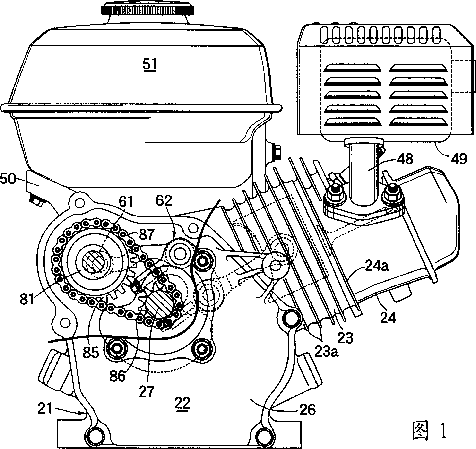
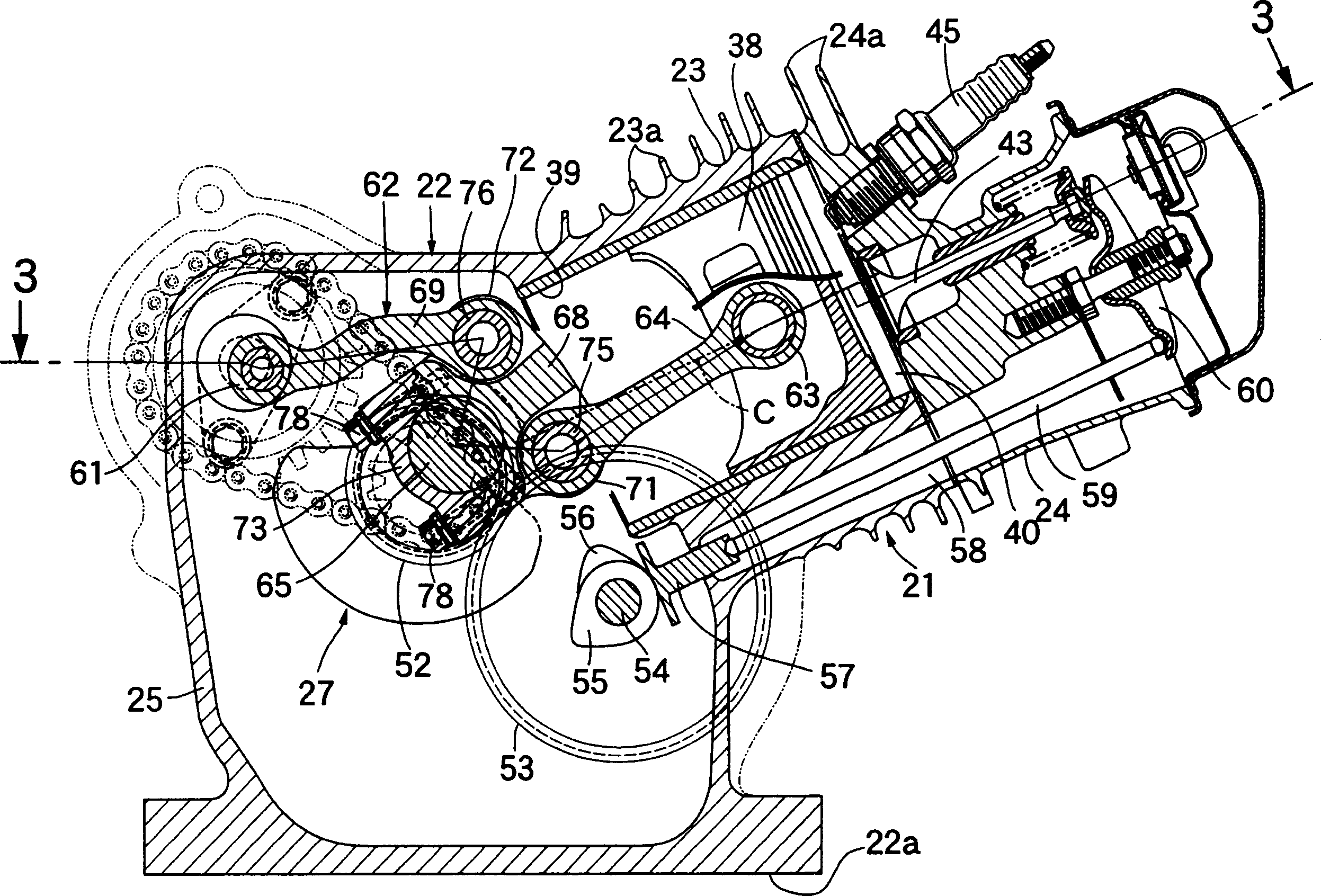
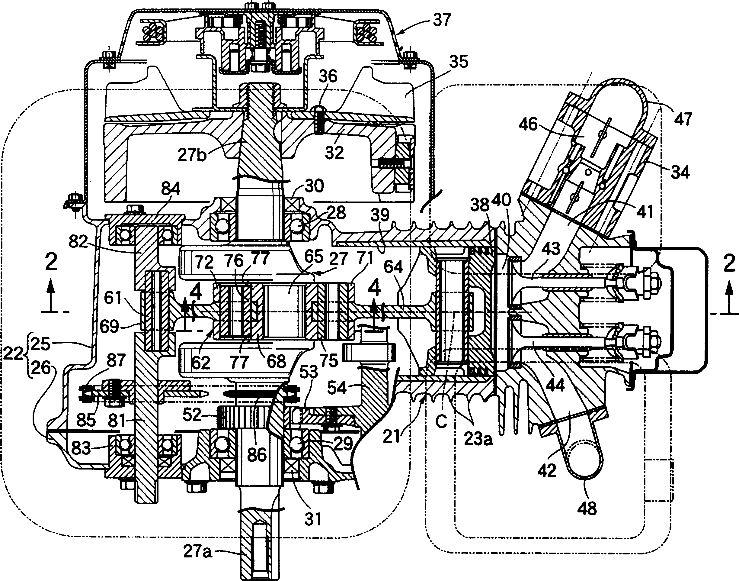
[0046] A first embodiment of the present invention will be described below with reference to FIGS. 1 to 7 . Refer to Figure 1 to image 3 , the engine according to the first embodiment of the present invention is an air-cooled single-cylinder engine for use in such as working equipment or the like, and this engine includes a body 21 consisting of a crankcase 22, from the crankcase 22 and a cylinder block 23 protruding slightly upwards on one side of the cylinder block 22, and a cylinder head 24 connected to a top of the cylinder block 23. On the outer surfaces of the cylinder block 23 and the cylinder head 24, a large number of air cooling fins 23a and 24a are provided. On the base of each of the various working machines is mounted a mounting surface 22 a on the lower surface of the crankcase 22 .

[0047] Crank case 22 comprises: a case body 25, and this case body forms an integral body with cylinder block 23 by casting; One side cover 26, is connected with an open end of c...


PUM


Abstract

The invention relates to an engine in which the piston stroke in the expansion stroke is greater than the piston stroke in the compression stroke. In order to ensure that the center of top dead center in each of the intake stroke and exhaust stroke is at the same level as the center of top dead center in the compression stroke, the following dimensions are determined according to the equation expressing the level of the piston pin so that in the intake stroke and The top dead center in each of the exhaust stroke and the top dead center in the compression stroke coincide with each other. These dimensions are: the length of the second arm; the length of the first arm; the length of the control rod; the length of the connecting rod; in the y-axis The length from the axis of the crankshaft to the axis of the rotation axis in the direction; the length from the axis of the crankshaft to the axis of the rotation axis in the direction of the x-axis; the deviation of the cylinder axis from the axis of the crankshaft in the direction of the y-axis; the first arm and the second The angle formed by the arms; the length between the axis of the crank shaft and the crank pin; the length of a straight line connecting the axis of the rotating shaft and the axis of the movable eccentric shaft; and the angle θp when the crank angle is "0".

Description

technical field [0001] The present invention relates to an engine comprising: a connecting rod, one end of which is connected to a piston through a piston pin; a first arm, one end of which is rotatably connected to the other end of the connecting rod , the other end of the first arm is connected to the other end of the crank shaft through a crank pin; the second arm, one end of the second arm is integrally connected with the other end of the first arm; the control rod, one end of the control rod Rotatably connected to the other end of the second arm; a movable eccentric shaft is installed between the eccentric positions of some rotating shafts to reduce the power transmission from the crank to the crank with a reduction ratio of 1 / 2. The rotating shaft, the movable eccentric shaft is connected to the other end of the control rod, and the piston stroke during the expansion stroke is greater than that during the compression stroke. Background technique [0002] Conventionall...

Claims


Application Information

Patent Timeline
Patent Type & Authority Applications(China)
IPC IPC(8): F01B9/04F01B31/14F02B41/04F02B75/04F02B75/16F02B75/32F02D15/02
CPCF02B41/04F02B75/048F02B75/16F02D15/02
Inventor 渡边生
Owner HONDA MOTOR CO LTD
Why Eureka
Try Eureka