Substrate processing appts.

A substrate processing device and substrate technology, which are applied in the fields of optics, instruments, electrical components, etc., can solve the problems of reduced utilization rate of developer, pollution of non-dissolved substances, and inability to process substrates, etc., to achieve reduced waste liquid volume, high utilization efficiency, The effect of reducing usage

Inactive Publication Date: 2003-10-08
DAINIPPON SCREEN MTG CO LTD
View PDF0 Cites 17 Cited by
  • Summary
  • Abstract
  • Description
  • Claims
  • Application Information

AI Technical Summary

Problems solved by technology

However, when a substance that reacts with the developer solution and does not dissolve in the developer solution is generated, when the developer solution is circulated for use, damage to the inner surface of the recovery tank 912, the liquid recovery pipe 908, or the liquid delivery pipe 914 will occur. Contamination of the inner surface, the inside of the pump 918, etc. by non-dissolved substances
In addition, there is a problem that the filter 916 attached to the liquid feeding pipe 914 is quickly clogged, and in the worst case, the substrate cannot be processed while circulating the developing solution.
[0014] On the other hand, when the developing solution is not circulated but discharged from the inner bottom of the developing treatment tank 110 to be discarded, although the above-mentioned problem does not occur, since the developing solution is sprayed from the developing solution when the substrate 1 does not pass directly under the developing solution spraying nozzle 116 The developer that is ejected from the nozzle 116 and flows to the inner bottom of the development treatment tank 110 is also discarded, so there is a problem that the utilization rate of the developer is lowered.
The above-mentioned problems not only exist in the development processing equipment, but also may occur in processing equipment such as cleaning, etching, and stripping processing.

Method used


Image

  • Substrate processing appts.
  • Substrate processing appts.
  • Substrate processing appts.

Examples


no. 2 Embodiment approach

[0127] Below, refer to the attached Figures 14 to 18 A second embodiment of the present invention will be described.

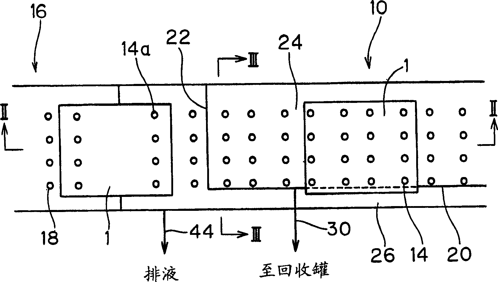
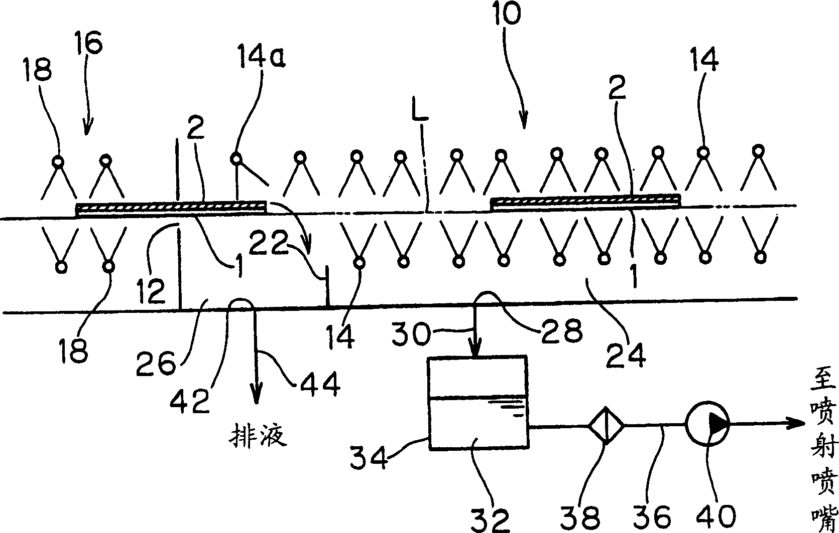
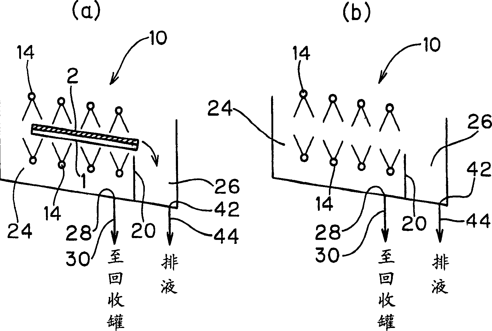
[0128] Figure 14 An example of the second embodiment of the present invention is shown, and it is a side view schematically showing a schematic configuration of a development processing apparatus which is one of substrate processing apparatuses. In such a development processing device, due to the structure and operation of the main part that performs the development processing and the corresponding Figure 20 It is the same as the existing device for explanation, so in Figure 14 Mark the same part with and Figure 20 The same reference numerals as used in , and their repeated descriptions are omitted.

[0129] In such a development processing apparatus, the inside of the development processing tank 110 is partitioned off below the developer spraying nozzle 116, and a recovery tank portion 122 is provided. In addition, instead of providing the recovery ...


PUM


Abstract

The purpose of the present invention is to provide a kind of apparatus that can reduce the used amount of processing liquid, have less liquid waste, maintain high processing efficiency, and suppress the contamination of component in liquid circulation path to the minimum. In the direction perpendicular to the conveying direction, the substrate 1 is conveyed in an inclined state relative to the horizontal plane. In the vicinity of the position right below the lower side edge of substrate on the inner bottom plane of the water washing processing tank 10, the isolation plate is erect along the substrate conveying direction so as to separate the inner bottom portion of the water washing processing tank and divide it into the followings: the recycling tank portion 24 for recycling pure water that expels from the pure water expelling nozzle 14 without flowing through the substrate face; and the exhausted liquid tank portion 26 for accommodating the used pure water that is expelled from pure water expelling nozzle to flow toward the lower substrate side and falls from the edge. Therefore, pure water recycled inside the recycling tank portion can be used again; and the used pure water flowing inside the exhausted liquid tank portion is exhausted.

Description

technical field [0001] The present invention relates to a substrate processing apparatus for performing cleaning, developing, etching, peeling, and other processes on substrates such as glass substrates for flat panel displays (FPDs), semiconductor wafers, and printed circuit boards while conveying them. Background technique [0002] In the manufacturing process of FPDs, semiconductor wafers, printed circuit boards, etc., for example, after the substrate is treated with a chemical solution, the substrate is washed with pure water to replace the chemical solution adhering to the substrate with pure water The following is a horizontal transfer processing device that uses transfer rollers to transfer substrates one by one in the horizontal direction, and sprays pure water on the substrates for water washing. An example of the general structure of such a processing device is shown in Figure 19 middle. [0003] Figure 19 The treatment apparatus shown in the figure is provided ...

Claims


Application Information

Patent Timeline
Patent Type & Authority Applications(China)
IPC IPC(8): B08B3/02G02F1/13H01L21/304H01L21/306
CPCH01L21/67051
Inventor 芳谷光明柳泽畅生丰田浩司山下永二铃木聪
Owner DAINIPPON SCREEN MTG CO LTD
Why Eureka
Try Eureka