Flame stand for stove and glass plate stove
A glass panel and flame technology, applied in the direction of stove/stove top, application, household stove, etc., can solve the problems of uneven secondary air, unsightly, disturbing secondary air, etc., to prevent adhesion and improve combustibility , clean up simple effect
Inactive Publication Date: 2003-10-15
RINNAI CORP
View PDF1 Cites 1 Cited by
- Summary
- Abstract
- Description
- Claims
- Application Information
AI Technical Summary
Problems solved by technology
Because this part is close to the burner, the radiated heat is at a relatively high temperature, and it is the place where the spilled soup or cooking food is easily scorched and accumulated because such things exist in the secondary air passage. At the outlet of the burner, it will definitely disturb the secondary air before entering the burner, so that the secondary air supplied to the burner will be uneven, which will definitely have a bad effect on the combustibility
[0005] In addition, although it is also considered to use a traditional flame support on the glass panel stove, the presence of the partition plate will give a bulky feeling to the flame support, which will detract from the beautiful appearance of the glass panel stove. , extremely unsightly
Method used
View moreImage
Smart ImageViewing Examples

Examples
Embodiment
[0024] Burner input
[0025]As can be seen from the above table, according to the embodiment of the present invention, the combustibility of the burner 3 is improved, and the thermal efficiency is also improved while reducing the amount of CO generated.
Login to View More PUM
 Abstract
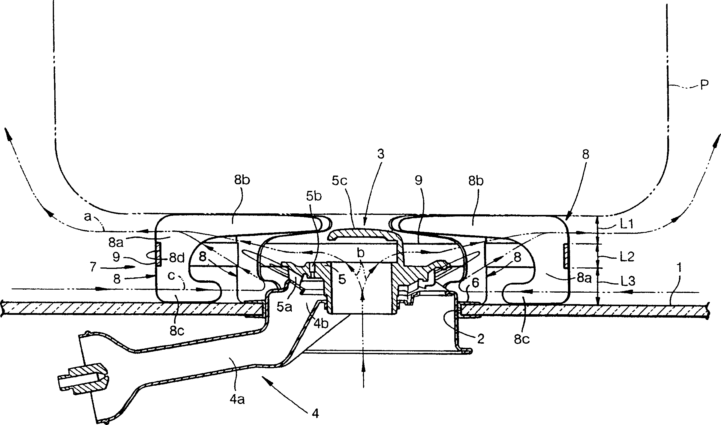
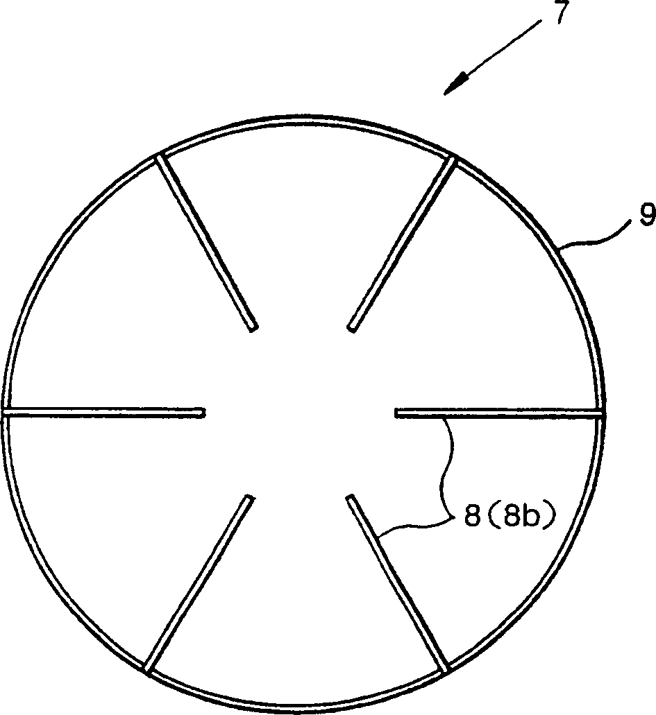
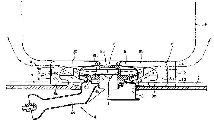
This invention provides a trivet and a glass top stove. An annular frame (9) is arranged on the trivet (7). The annular frame (9) is located below the upper edge of the trivet claws (8) and above the lower ends of the foot portions (8a) of the trivet claws (8), and is formed by a band-like plate extending up and down along the width direction. A plurality of trivet claws (8) are fixed to the annular frame (9) at the respective foot portions (8a) of the trivet claws. The combustion exhaust gas of the burner (3) flows through an upper space of the annular frame (9) and exits to the exterior. The secondary air flows smoothly from a lower space of the annular frame (9) along the glass top panel (1) to the burner part. The trivet of the invention separates the flow of the combustion exhaust ga s and the flow of the secondary air to enhance the combustibility of a burner and that is suitable for a glass top stove.
Description
technical field [0001] The present invention relates to a flame holder for a stove, which is provided with a plurality of flame holder claws spaced apart from each other in the circumferential direction, and a glass panel stove using the flame holder. Background technique [0002] As we all know, according to Japanese Patent Laid-Open No. 58-102032, the flame support for stoves in the past is provided with a wide annular partition in the diameter direction, and makes it under the upper edge of the flame support claw and the legs of the flame support. Above the lower end, a plurality of flame support claws are inserted and fixed on the dividing plate at the legs. The flame support can divide the combustion exhaust flow discharged from the burner and the secondary air flow supplied to the burner into upper and lower parts through the partition plate, which is beneficial to improve the combustibility of the burner. [0003] In addition, the above-mentioned flame support is use...
Claims
Login to View More Application Information
Patent Timeline
 IPC IPC(8): F24C15/10F24C3/02
CPCA47B13/12F24C3/008F24C15/107
Inventor 重野秀树
Owner RINNAI CORP
Features
- R&D
- Intellectual Property
- Life Sciences
- Materials
- Tech Scout
- Unparalleled Data Quality
- Higher Quality Content
- 60% Fewer Hallucinations
Learn More Browse by: Latest US Patents, China's latest patents, Technical Efficacy Thesaurus, Application Domain, Technology Topic, Popular Technical Reports.
© 2025 PatSnap. All rights reserved.Legal|Privacy policy|Modern Slavery Act Transparency Statement|Sitemap|About US| Contact US: help@patsnap.com