Drilling bit

A drill bit and flute technology, applied in the direction of drill repair, twist drill, drill tool accessories, etc., can solve the problems of reducing the precision of through holes, center position deviation, etc., and achieve good inner wall roughness, reduced processing load, high straightness progressive effect

Inactive Publication Date: 2003-12-10
UNION TOOL +1
View PDF0 Cites 2 Cited by
  • Summary
  • Abstract
  • Description
  • Claims
  • Application Information

AI Technical Summary

Problems solved by technology

[0018] In addition, if the central front end of the drill bit 33 cannot be sharpened, the center position of the drill bit 33 tends to deviate when the drilling starts, which naturally reduces the accuracy of the through hole.

Method used


Image

  • Drilling bit
  • Drilling bit
  • Drilling bit

Examples


Embodiment Construction

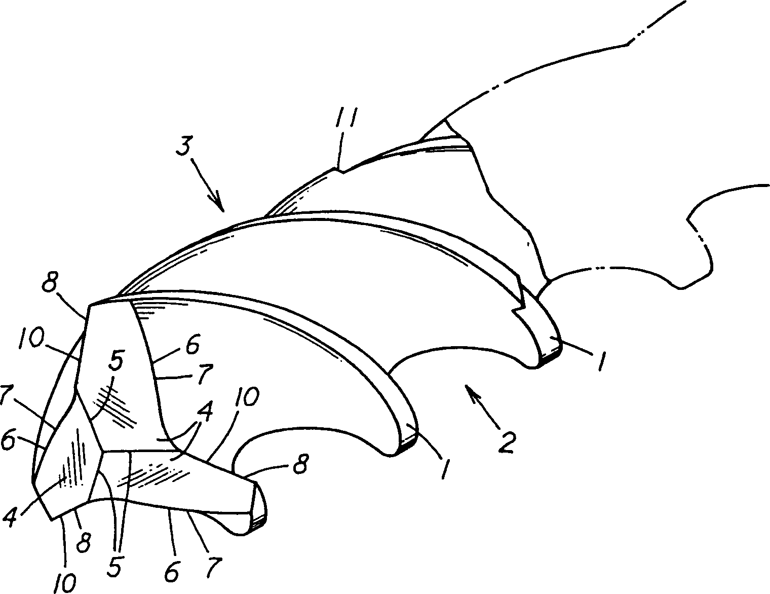
[0045] Figure 3-5 One embodiment of the present invention is shown and described below.

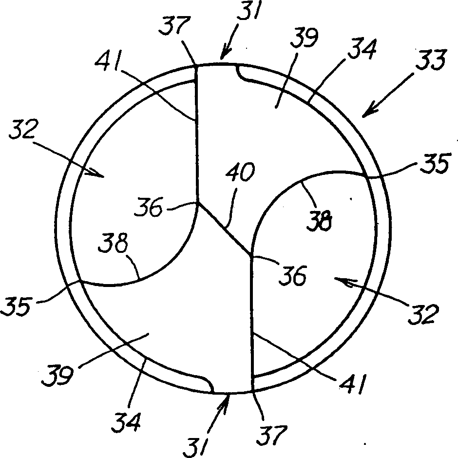
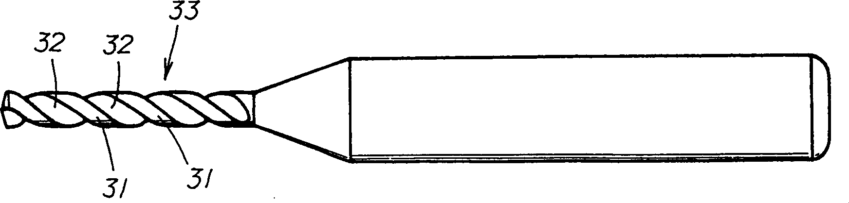
[0046] In this embodiment, a plurality of chip flutes 2 are spirally provided on the outer peripheral surface, and edge portions 1 are provided between the chip flutes 2. In addition, a cutting edge 8 is provided at the front end. In the drill bit 3, the drill bit 3 is made of cemented carbide, and three flutes 2 are provided. On the front end portion of the drill bit 3, the edge portion 1 and the adjacent edge portion 1 are connected by the relief surface 4 as the front end portion of each edge portion 1. The relief surface 4 intersects to form three chisel edges 5, the sharp point of the front end is formed by the intersection of these three chisel edges 5, and the surface connected to the cutting edge 8 described in the above-mentioned edge 1 ( On the surface opposite to the inclined surface 10 ), a protruding portion 7 extending along the extending direction of the chip flute 2 is pro...


PUM

PropertyMeasurementUnit
diameteraaaaaaaaaa

Abstract

The object of the present invention is to provide a drill that is long in length and has a small diameter, and at the same time, features a high strength capable of advancing straight forwards as well as being capable of drilling holes having excellent inner wall roughness so as to enhance the applicability of the drill. The solution of the present invention is a drill 3 comprising plural chip discharge grooves 2 helically formed on a peripheral surface, a margin section 1 provided between the chip discharge grooves 2, and cutting edge 8 formed on a tip thereof. The drill 3 is made of ultra-hardened alloy and includes more than three chip discharge grooves 2. A flank 4 is provided at a front face of each of the margin section 1, to form more than three chisel edges 5 by crossing adjoining chisel edges. Intersections of the three chisels 5 form an acute point. An opposite face of a cutting face 10 of the margin section 1 is provided with a swelling section 7 extending towards the chip discharge grooves 2.

Description

technical field [0001] The invention relates to a drill bit for drilling precision holes on workpieces. Background technique [0002] A printed circuit board (hereinafter referred to as a printed circuit board) on which electronic components are mounted is formed by laminating copper foil on a fiber-reinforced resin. A metal plating layer is formed on the inner wall, and then, the copper foil on the surface of the printed substrate is etched to form a printed circuit, and the printed circuit and the copper foil of the lower layer are electrically conductive through the metal plating layer, and then, electronic soldering such as LSI is soldered on the above-mentioned through hole. components to form a printed circuit board. [0003] However, in recent years, along with the improvement in performance and miniaturization of electronic equipment, there has been an increasing demand for high-density mounting on printed circuit boards. Due to this requirement, the reduction in d...

Claims


Application Information

Patent Timeline
Patent Type & Authority Applications(China)
IPC IPC(8): B23B51/00H05K1/02
CPCB23B41/14B23B51/02B23B2251/408B23B2251/44
Inventor 涌井秀夫高桥昭一安达健中田和人高井豪
Owner UNION TOOL
Why Eureka
Try Eureka