Respirator

A technique for breathing devices and inspiratory valves, applied in the direction of respiratory protection devices, valve devices, breathing masks, etc., which can solve problems such as prone to failure, complex mask structure, and difficulty in installing differential pressure sensors, so as to achieve less failure and simple structure Effect

Inactive Publication Date: 2003-12-31
KOUKEN CO LTD
View PDF2 Cites 18 Cited by
  • Summary
  • Abstract
  • Description
  • Claims
  • Application Information

AI Technical Summary

Problems solved by technology

[0010] However, if the supply voltage of the blower is set above the maximum air flow of the blower at the time of suction, the power consumed by the blower will increase unnecessarily, and the consumption of the filter material will also be accelerated.
Furthermore, the use of a filter material with a higher ventilation resistance requires more blower torque, so the power consumption increases in proportion to the ventilation resistance of the filter material used.
[0011] (3) In the existing dust mask equipped with a blower, because air is also supplied to the inside of the dust mask during exhaust, a positive pressure is generated in the face of the dust mask, especially if the air supply volume of the blower is set at the breathing When it is above the maximum peak value, the pressure inside the surface is very high, and the exhaust resistance will become larger
[0014] However, in this breathing apparatus, since the first flow path connected to one side of the pressure responsive part (diaphragm) on the downstream side of the blower and the second flow path connected to the other side of the pressure responsive part on the upstream side of the blower must be connected to the other side of the pressure responsive part. The original inhalation passages are set separately, so not only the structure of the mask becomes very complicated, but also it is difficult to install the differential pressure sensor compactly
Furthermore, because the opening of the first flow path or the second flow path must be formed between the filter and the blower, the overall size of the breathing apparatus has to be enlarged.
In addition, although the diaphragm is used in the pressure response part, it is prone to failure due to the fatigue of the diaphragm, and it is difficult to maintain the set value of the reflected pressure of the differential pressure sensor.

Method used


Image

  • Respirator
  • Respirator
  • Respirator

Examples


Embodiment Construction

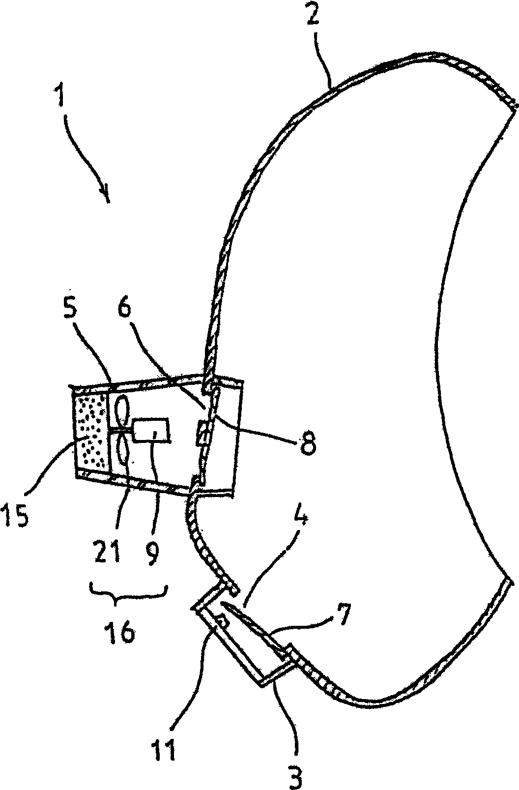
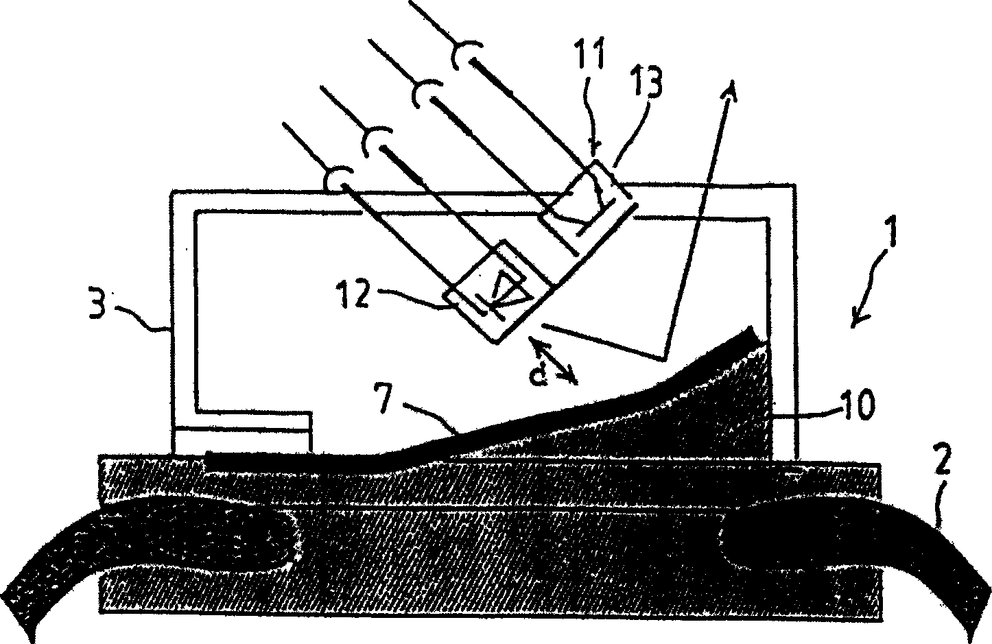
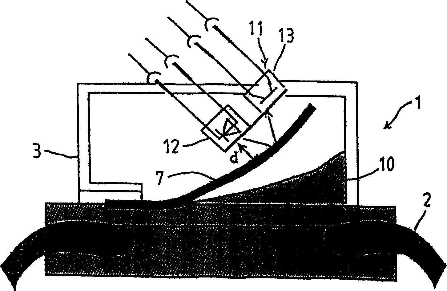
[0030] refer to Figure 1 to Figure 4 , the first embodiment of the present invention will be described.

[0031] Such as figure 1 As shown, an exhaust port 4 and an inhalation port 6 are formed on the surface body 2 of the breathing apparatus 1 . The outside of the exhaust port 4 is covered by the exhaust valve cover 3 arranged on the surface body 2 . The outside of the suction opening 6 is covered by a filter material cover 5 arranged on the surface 2 from the outside.

[0032] The exhaust port 4 is equipped with an exhaust valve 7 that is opened during exhaust and closed during suction. The suction port 6 is equipped with an air suction valve 8 that is closed during exhaust and opened during suction.

[0033] The filter material 15 and the air blower 16 are arrange|positioned at the exterior of the suction valve 8 and the inside of the filter material cover 5 in a facing posture. The blower 16 is composed of an impeller 21 and a motor 9 that drives the impeller 21 to r...


PUM


Abstract

A respirator (1), wherein an inlet (6) and an outlet (4) are formed in a surface body (2) closably by an intake valve (8) and an exhaust valve (7), the intake valve (8) is opened and the exhaust valve (7) is closed when a person wearing the respirator (1) inhales air, and the closing operation of the exhaust valve (7) is detected by a photo interrupter (11) to feed a power to a motor (9) for driving a blower (16).

Description

technical field [0001] The present invention relates to a breathing apparatus suitable for full-face masks, half-face masks, and the like for the purpose of dustproofing and poisoning. Background technique [0002] Workers who work in hazardous dust or toxic gas atmospheres usually wear dust or gas masks. After the dangerous and harmful substances contained in the air are removed with the filter of the dust mask, activated carbon and other filter materials, the purified air is inhaled. [0003] However, generally speaking, for some filter materials such as filters and canisters, the greater the purification effect, the greater the ventilation resistance. [0004] In particular, since the radioactive dust in nuclear power plants, the harmful dust of dioxin contained in the site of dismantling garbage incineration furnaces, and the harmful gases generated by various other operations invade the human body, it will have a great adverse effect on health. The filter material use...

Claims


Application Information

Patent Timeline
Patent Type & Authority Applications(China)
IPC IPC(8): A62B9/00A62B18/00A62B18/10F16K15/16F16K37/00
CPCA62B18/006A62B18/10A62B7/00
Inventor 栗山智
Owner KOUKEN CO LTD
Why Eureka
Try Eureka