
Pump

A pump chamber and moving wall technology, which is applied in the field of pumps with high reliability and large flow, can solve problems such as pressure loss, pump inoperability, and increase in reverse flow, so as to achieve good driving efficiency and prevent consumption.

Inactive Publication Date: 2004-01-14
SEIKO EPSON CORP
View PDF3 Cites 8 Cited by
  • Summary
  • Abstract
  • Description
  • Claims
  • Application Information

AI Technical Summary

Problems solved by technology

[0010] However, there is such a problem in the structure described in Patent Document 1: check valves need to be installed in both the inlet passage and the outlet passage, and there will be a large pressure loss when the fluid passes through the two check valves.
However, in the structure described in Patent Document 2, there is a problem that it is difficult to realize a small and high output pump because it can only be driven at a low frequency as described above.
[0013] The structure described in Patent Document 3 has such a problem: in order to form a net flow rate of the fluid passing through the compression part in one direction due to the difference in the pressure drop caused by the direction of the liquid flow as the volume of the pump chamber increases and decreases, the flow rate increases with the pump outlet. The external pressure (load pressure) on the side increases, and the reverse flow increases, so that the pump cannot work under high load pressure

Method used


Image

  • Pump
  • Pump
  • Pump

Examples


Embodiment 2

[0130] Such as Figure 8 As shown, the driving device 20 of this embodiment is provided with: a cycle control circuit (cycle control device) 22 and a voltage waveform generating circuit 24 .

[0131] The voltage waveform generating circuit 24 has a following Figure 6 With the same structure as the block diagram of , every time a trigger signal described later is received, the voltage waveform set before receiving the trigger signal is generated once.

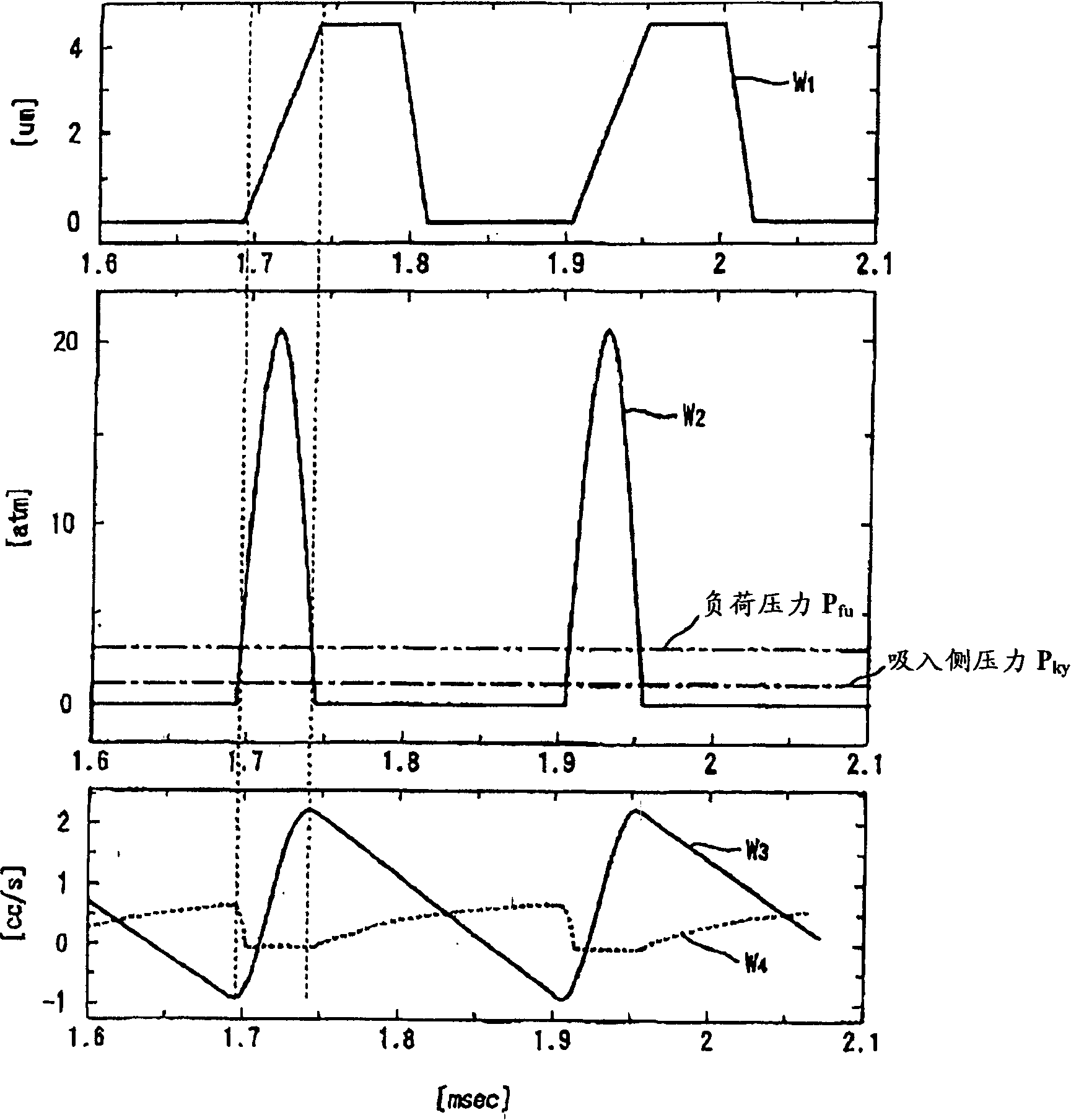
[0132] The cycle control circuit 22 is provided with a pressure-cycle conversion circuit 22d that generates a trigger signal based on a detection value of a pressure sensor (pump pressure detection device) 28 provided in the pump.

[0133] Figure 9 The processing procedure of the pressure-period converting circuit 22d is shown in a flowchart.

[0134] First, in step S4, the threshold value P of the pressure is set sh . The threshold P sh Use the suction side pressure P in the pressure sensor 28 ky Add a value above the ...

Embodiment 3

[0147] The figure is to represent Figure 8 The flow chart of the processing sequence of the pressure-period conversion circuit 22d shown, since following Figure 8 The structures shown are the same, and the block diagram of the driving device 20 is omitted.

[0148] First, in step S30 , a period T1 among a plurality of periods Ti (i=1, 2, 3 . . . ) of the diaphragm 5 is selected. Also, after the next time, another period Ti is selected instead.

[0149] Then, go to step S32 to confirm whether the calculation of the calculation value Fi described later for all periods Ti has been completed, if not, go to step S38, and if finished, go to step S36.

[0150] In step S38, a trigger signal Si is output.

[0151] Next, the process goes to step S44, and the pressure Pin of the pump chamber 3 is measured by the pressure sensor 28.

[0152] Next, the process proceeds to step S46, and it is checked whether the relationship between the reference value (predetermined value) Pa and the...

Embodiment 5

[0169] Figure 13 The drive device 20 of this embodiment shown is provided with a cycle control circuit (cycle control device) 22 and a voltage waveform generation circuit 24 . The cycle control circuit 22 is provided with: the displacement of the trigger signal is generated based on the detection value of the displacement sensor 30 that detects the displacement state of the check valve 4 opened and closed by the pressure difference at the inlet passage 1 in the pump. Period conversion circuit 22e.

[0170] Figure 14 It is a flowchart showing the processing procedure of the displacement-period conversion circuit 22e.

[0171] First, in step S60, a threshold value X corresponding to the displacement amount when the check valve 1 closing the inlet passage 1 is substantially closed is set. 0 .

[0172] Next, go to step S62, and output a trigger signal.

[0173] Next, it goes to step S64, and it is confirmed whether one output of the voltage waveform is completed, and if it ...


PUM


Abstract

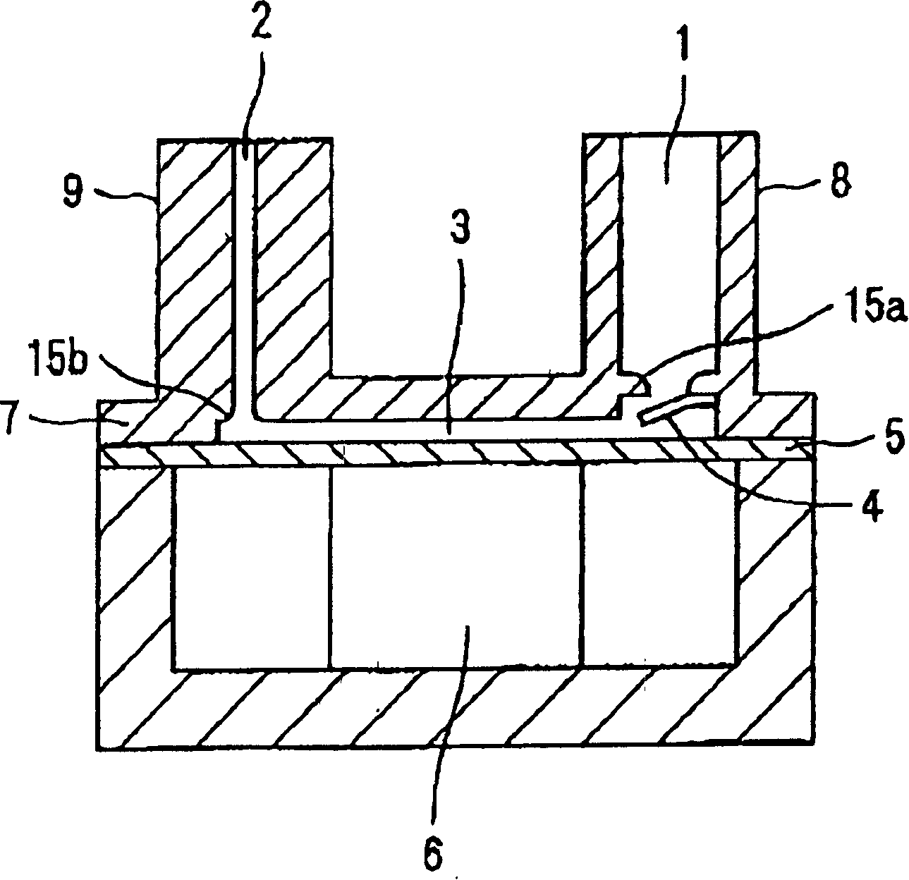
The invention provides a pump with high driving efficiency in which the number of mechanical switching valves is decreased to reduce pressure loss and increase reliability, and which is ready for high load pressure and high-frequency driving, and which increases the discharged fluid volume for one cycle of pumping. A circular diaphragm 5 arranged on the bottom of a casing 7 has the outer edge fixed to the casing 7. The diaphragm 5 includes a piezoelectric element 6 to move the diaphragm on the bottom surface thereof. The space between the diaphragm 5 and the top wall of the casing 7 serves as a pump chamber 3, wherein a suction channel 1 and a discharge channel 2 are opened to the pump chamber, the suction channel having a check valve 4 serving as a fluid resistive element and the discharge channel being always communicated with the pump chamber, even during the operation of the pump. In the pump, the activation of the piezoelectric element is controlled by a cycle control device so as to provide the cycle of the diaphragm in which the volume and the pressure of the discharged fluid of the pump are increased.

Description

technical field [0001] The present invention relates to a positive displacement pump which moves a fluid by changing the volume of a pump chamber by a plunger or a diaphragm, and more particularly relates to a pump with high reliability and a large flow rate. Background technique [0002] As a conventional pump of this type, a structure in which a check valve is provided between an inlet passage, an outlet passage and a volume-variable pump chamber is generally adopted. [0003] (For example, refer to Patent Document 1) [0004] In addition, as a pump structure for forming unidirectional flow by utilizing viscous resistance of fluid, there is a structure in which a valve is provided in the outlet passage, and when the valve is opened, the inlet passage has a higher fluid resistance than the outlet passage. (For example, refer to Patent Document 2) [0005] In addition, as a pump structure that improves the reliability of the pump without using a movable member in the valve...

Claims


Application Information

Patent Timeline
Patent Type & Authority Applications(China)
IPC IPC(8): F04B9/00F04B43/04F04B49/06
CPCF04B49/065F04B43/046
Inventor 高城邦彦濑户毅
Owner SEIKO EPSON CORP
Learn More