Vacuum processing device

A technology of vacuum treatment device and vacuum treatment chamber, which is applied in the direction of gaseous chemical plating, coating, electrical components, etc., which can solve the problems of complicated maintenance operations, reduced device work rate, and high maintenance frequency, so as to reduce the generation of dust , increase output rate, shorten the effect of time

Inactive Publication Date: 2004-01-14
TOKYO ELECTRON LTD
View PDF0 Cites 9 Cited by
  • Summary
  • Abstract
  • Description
  • Claims
  • Application Information

AI Technical Summary

Problems solved by technology

If the degree of corrosion and contamination is more pronounced, the frequency of this repair will be more
Due to the complex structure of the device, the maintenance operation is very complicated and takes a long time
If the device is stopped frequently for a long time, the so-called problem of lowering the operating rate of the device and lowering the productivity will occur.

Method used


Image

  • Vacuum processing device
  • Vacuum processing device
  • Vacuum processing device

Examples


Embodiment Construction

[0016] Preferred embodiments of the vacuum processing apparatus of the present invention will be described below with reference to the drawings. In the following description and drawings, the same reference numerals are assigned to components having the same functional structure, and redundant descriptions are omitted.

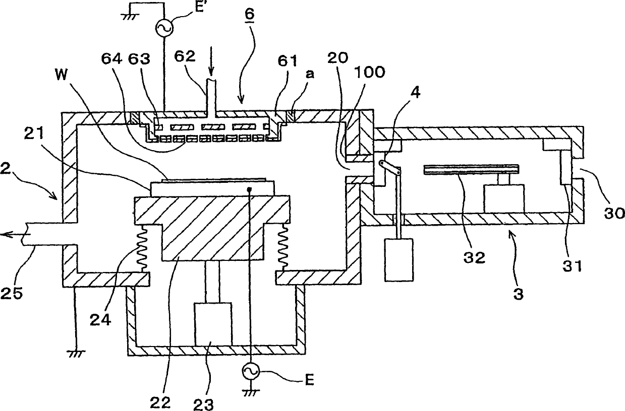
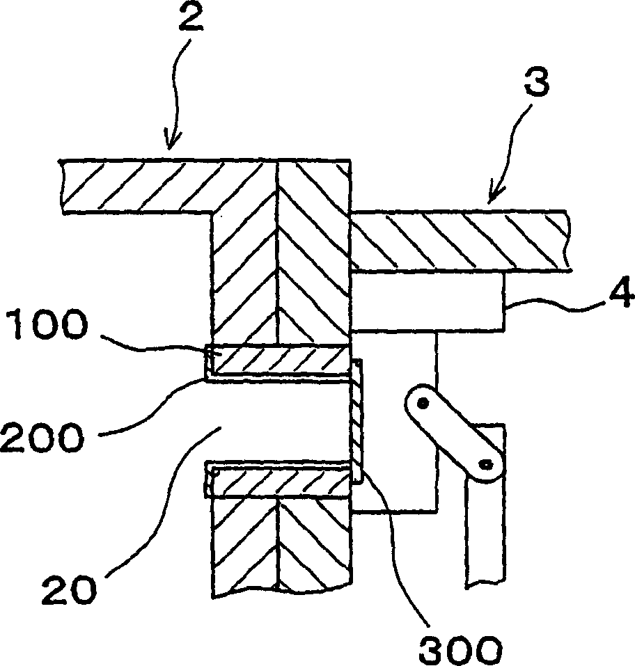
[0017] FIG. 1 is an overall configuration diagram of a vacuum processing apparatus of the present invention suitable for use in a plasma etching processing apparatus. The processing chamber 2 is a vacuum chamber with an airtight structure, and the processing chamber is grounded. The pre-vacuum chamber 3 has a load-lock function in order to prevent the inside of the processing chamber 2 from being directly exposed to the atmosphere. The processing chamber 2 and the pre-vacuum chamber 3 are connected together by a transfer port 20 formed on the chamber wall, and the wafer W is transferred through the transfer port 20 .

[0018] A susceptor 21 on which a wafer ...


PUM

PropertyMeasurementUnit
thicknessaaaaaaaaaa
thicknessaaaaaaaaaa
thicknessaaaaaaaaaa

Abstract

Maintenance work on an apparatus is facilitated, the maintenance cycle is extended and an improvement in throughput is achieved. A processing chamber 2 and an auxiliary vacuum chamber 3 are connected via a transfer port 20 formed through their wall surfaces. At the inner wall of the transfer port 20, a detachable gate liner 100 constituted of a plurality of members is installed. The maintenance work at the inner wall of the transfer port is facilitated since the gate liner 100 alone simply needs to be disengaged to be washed, replaced or the like. Insulating films 200 and 300 constituted of a rare earth oxide spray-deposit film with high plasma erosion resistance are used to coat the surface of the gate liner 100 and the surface of a gate valve 4 over the area covering the transfer port 20. As a result, damage attributable to plasma does not occur readily at these surfaces, and the extent of metal contamination and dust generation is lowered.

Description

technical field [0001] The present invention relates to a vacuum processing apparatus for performing etching, film formation, etc. on a target object such as a semiconductor wafer or a substrate for a liquid crystal display. Background technique [0002] In the processing steps of semiconductor devices and the like, there are various processes such as etching, film formation processing, ashing, and sputtering, and various processing apparatuses are used corresponding to these processes. In such a processing apparatus, a pre-vacuum chamber having a load-lock function is connected to an airtight processing chamber so that impurities in the atmosphere cannot enter the processing chamber. The processing chamber and the pre-vacuum chamber are connected by a transfer port formed on the wall, and the object to be processed is transferred through the transfer port. Therefore, freely openable and closable valves called gate valves are provided at the transfer port on the atmospheric...

Claims


Application Information

Patent Timeline
Patent Type & Authority Applications(China)
IPC IPC(8): C23C16/44H01J37/32H01L21/00
CPCH01L21/67028H01J37/32477C23C16/4404H01J37/32743H01L21/67126
Inventor 今福光祐肥田刚
Owner TOKYO ELECTRON LTD
Why Eureka
Try Eureka