Beam emittance automatic measurement and particle beam focusing automatic regualting method and apparatus

An automatic adjustment and automatic measurement technology, which is applied in radiation/particle processing, program control devices, instruments, etc., can solve the problems of unseen combination, achieve the effect of improving beam quality and reducing the chance of collision

Inactive Publication Date: 2004-01-28
INST OF PLASMA PHYSICS CHINESE ACAD OF SCI
View PDF0 Cites 4 Cited by
  • Summary
  • Abstract
  • Description
  • Claims
  • Application Information

AI Technical Summary

Problems solved by technology

However, there is no method and device that combines detection and focusing and performs automatic control at the same time.

Method used


Image

  • Beam emittance automatic measurement and particle beam focusing automatic regualting method and apparatus
  • Beam emittance automatic measurement and particle beam focusing automatic regualting method and apparatus
  • Beam emittance automatic measurement and particle beam focusing automatic regualting method and apparatus

Examples


Embodiment Construction

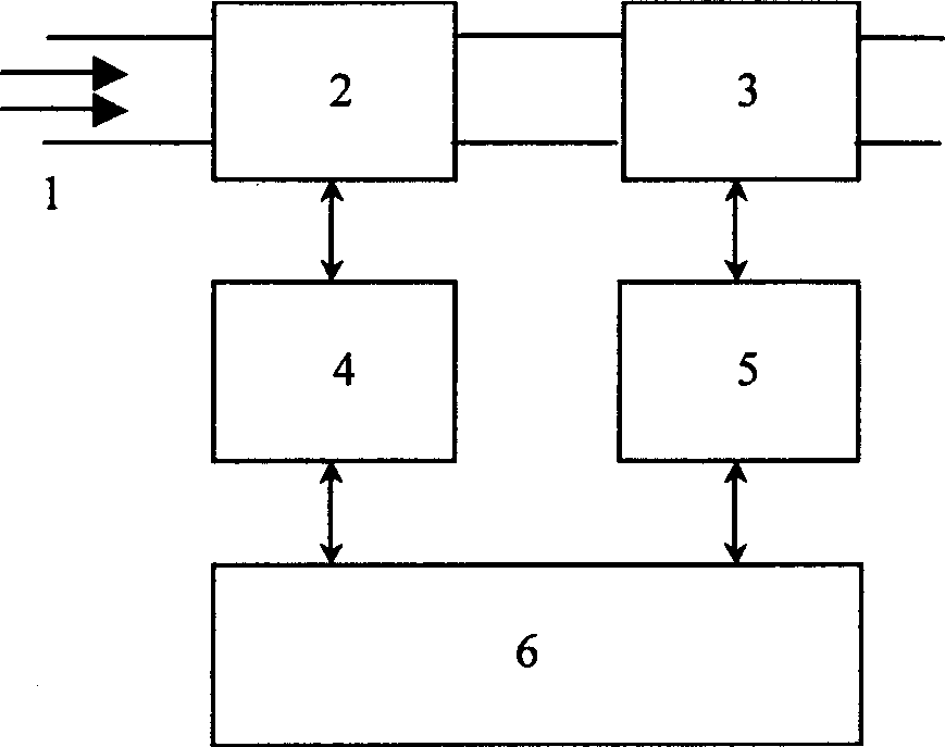
[0009] The beam emittance measurement can use the pepper screen method or the OTR method as the measuring instrument (device) [2] of the present invention, which is connected with the input data controller (device) [4], and the input data controller [4] is controlled by A / The D converter and the sensor are composed. The A / D converter converts the measured lateral emissivity electrical signal into a digital signal of the computer. The sensor receives the instructions of the computer [6] to drive the mechanical transmission to work, and drives the measuring instrument [2] ] into or out of the beam tube. The focusing lens [3] can be a quadrupole lens, a single lens, etc. It is connected with the output data controller [5], and the output data controller [5] includes a D / A converter and a sensor, and the D / A converter is a computer [6] The digital signal is converted into an electrical signal, and the electromagnetic parameters of the focusing lens are controlled by the sensor to...


PUM


Abstract

Comparing with previous research, the invention combines measuring and focusing beam flux. Computer (PC) controls automatic measuring and focusing. Computer sends the measuring commands, reads data, obtains parameters of transmittance, from which the beam flux parameter and focusing parameter are obtained through calculation. The focusing parameter is passed to focusing device (lens) in order to improve quality of beam flux. As the quality of beam flux is raised, the chance of collision between beam flux and viewfinder is reduced. The beam spot will reduced to 2-3 mum or even less. The invention can be applied to monitoring beam flux and improving quality of beam in accelerator automatically, especially the device needed of small beam spot as well as ion optics, electron optics and particle accelerator.

Description

Technical field: [0001] The invention belongs to the fields of radiation biology, ion optics, electron optics and particle accelerators. Background technique: [0002] In the field of radiation biology, accurate positioning is a very important technology in the single-particle microbeam system for positioning and irradiating cells. To accurately position and irradiate cells, the beam spot at the exit of the single-particle microbeam system must be reduced to a certain degree. At present, the common method used by countries all over the world is to use an aimer with an aperture of the order of microns, and generally a beam spot with a diameter of 5-10 μm can be obtained. The diameter is basically about 5 μm. To further reduce the exit beam spot of the single particle beam device, it is necessary to study and discuss the beam quality optimization of the single particle beam device and the reasons that affect the beam quality. There are many factors affecting the beam qualit...

Claims


Application Information

Patent Timeline
Patent Type & Authority Applications(China)
IPC IPC(8): G06F7/00G06F9/44G21K1/00
Inventor 吴瑜余增亮王绍虎胡素华陈斌张束清李军吴李君
Owner INST OF PLASMA PHYSICS CHINESE ACAD OF SCI
Why Eureka
Try Eureka