Semi-intelligent position searching and machining method of digitally controlled machine tool

A CNC machine tool and intelligent technology, applied in metal processing equipment, metal processing machine parts, manufacturing tools, etc., can solve problems such as expensive machine tools and complex machine tool structures, and achieve low manufacturing and design costs, simple process equipment, and concentrated processes Effect

Inactive Publication Date: 2004-02-11
WUHAN TEXTILE UNIV
View PDF0 Cites 11 Cited by
  • Summary
  • Abstract
  • Description
  • Claims
  • Application Information

AI Technical Summary

Problems solved by technology

[0003] ① For workpieces with large batches or complex shapes, special fixtures must be used
[0012] This new type of machining center adopts a parallel closed-chain multi-degree-of-freedom feed system and is directly driven by a linear motor. Therefore, it is necessary to make the machine tool spindle (driving the tool) move at a high speed with six degrees of freedom relative to the workpiece. The machine tool with multi-coordinate control function makes the structure of the machine tool relatively complicated, and the machine tool is very expensive (more than one million yuan)

Method used


Image

  • Semi-intelligent position searching and machining method of digitally controlled machine tool
  • Semi-intelligent position searching and machining method of digitally controlled machine tool
  • Semi-intelligent position searching and machining method of digitally controlled machine tool

Examples


Embodiment 1

[0041] The method of semi-intelligent positioning processing of CNC machine tools is carried out according to the following specific steps:

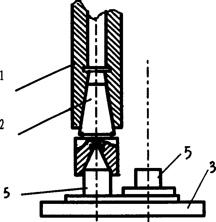
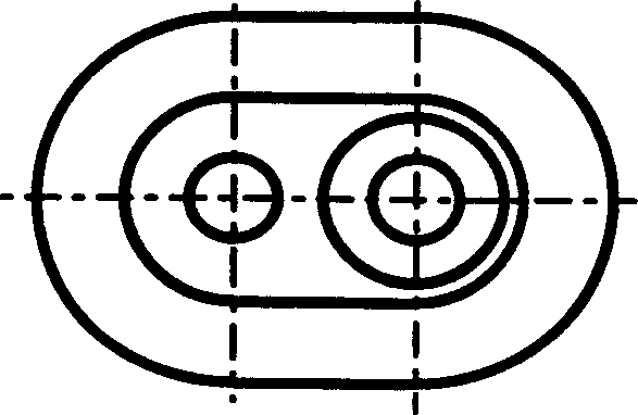
[0042] Test sample: gear pump cover, such as figure 1 and figure 2 as shown,

[0043] 1) Input the NC program prepared in advance for workpiece processing into the NC machine tool system.

[0044] 2) First place the large plane of the workpiece blank on the machine table at random, and fix the workpiece on the table with a pressure plate, T-slot screws (or magnetic chuck).

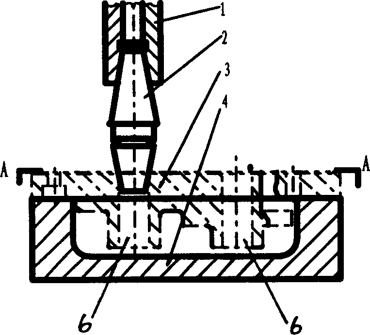
[0045] 3) Set the position finder with inner cone on the machine tool spindle 1, jog the worktable, so that the inner cone of the position finder 2 is correctly set on the first boss 5 of the workpiece 3, and record it by the CNC system Its coordinate value (X 1 , Y 1 ). Raise the taper sleeve to pull it out from boss 5. Such as figure 1 , figure 2 shown.

[0046] 4) Jog the workbench again, so that the inner taper sleeve of the finder is correctly set ...

Embodiment 2

[0061] Embodiment 2: basically the same as Embodiment 1, the difference is because the workpiece is placed arbitrarily on the machine tool, therefore,

[0062] The Φ angle at this time is different from Example 1.

[0063] The second wax model test: if figure 1 , figure 2 as shown,

[0064] Place the second gear pump wax model blank on the machine table at will, and fix it on the table with T-slot screws and pressure plates, and repeat the above process. Get the following data:

[0065] x 1 =-10.564Y 1 =-66.252

[0066] x 2 =-70.348Y 2 =-67.196

[0067] ΔX=X 2 -X 1 =-59.784

[0068] ΔY=Y 2 -Y 1 =-0.94

[0069] Φ=arc tgΔY / ΔX=0.9(degrees)

[0070] Enter the Φ angle into the program, load the corresponding tool on the spindle, turn on the working cycle button, the machine tool executes the program, and completes all processing.

Embodiment 3

[0071] Embodiment 3: It is basically the same as Embodiment 2, except that the Φ angle is different. Second trial of the second wax pattern test:

[0072] Loosen the wax pattern processed above, move the workpiece, and re-press and fix it on the machine table. Repeat the test. Get the following data:

[0073] x 1 =-10.560Y 1 =-71.892

[0074] x 2 =-70.344Y 2 =-66.252

[0075] ΔX=X 2 -X 1 =-59.784

[0076] ΔY=Y 2 -Y 1 =5.64

[0077] Φ=arc tgΔY / ΔX=-5.389(degree)=354.611(degree)

[0078] Input the Φ angle into the program, load the corresponding tool on the spindle, turn on the working cycle button, and the machine tool executes the program. Since the surface required by the workpiece has been processed, during the second processing, the machine tool’s The cutting process is basically chipless machining.


PUM


Abstract

The present invention relates to the machining of mechanical parts in digitally controlled machine tool. The semi-intelligent position searching and machining method in digitally controlled machine tool features that the position searching device inside the main shaft hole is used to search the coordinates of two characteristic surfaces O1(X1, Y1) and O2(X2, Y2) or orientation O1O2 of the workpiece; the rotation angle between the workpiece coordinate system and the machine tool coordinate system is calculated and input into the digital control program, and the rotation angle may be calculated automatically in the digital control system with relatively powerful function; and the workpiece may be program machined via coordinate translation of the cutting point and starting the digital control program. The present invention has the features of simple equipment, high machining precision and simple operation.

Description

technical field [0001] The invention relates to a method for machining mechanical parts on a numerically controlled machine tool. Background technique [0002] For a long time, the manufacturing operation mode of "positioning-processing" has been widely used in the processing of parts in the world's machinery manufacturing industry. The core of the "positioning-processing" mode is that the parts to be processed must first be accurately positioned on the machine tool in strict accordance with the design and process requirements of the workpiece, so as to ensure that the relative positions of the workpiece, machine tool, and tool are consistent with the predetermined state, thereby ensuring Process qualified products. Therefore, the correct positioning of the machined parts will be the key to this manufacturing mode. [0003] ① For workpieces with large batches or complex shapes, special fixtures must be used. Each process has matching fixture positioning and clamping eleme...

Claims


Application Information

Patent Timeline
Patent Type & Authority Applications(China)
IPC IPC(8): B23Q16/00
Inventor 张仙珍
Owner WUHAN TEXTILE UNIV
Why Eureka
Try Eureka