Ferroelectric memory device and its programming method

A ferroelectric storage and device technology, applied in static memory, read-only memory, digital memory information and other directions, can solve problems such as non-recovery

Inactive Publication Date: 2004-03-03
SK HYNIX INC
View PDF0 Cites 3 Cited by
  • Summary
  • Abstract
  • Description
  • Claims
  • Application Information

AI Technical Summary

Problems solved by technology

In redundant processing methods with conventional metal/polysilicon wire

Method used


Image

  • Ferroelectric memory device and its programming method
  • Ferroelectric memory device and its programming method
  • Ferroelectric memory device and its programming method

Examples


Example Embodiment

[0043] Hereinafter, the present invention will be described in more detail with reference to the accompanying drawings.

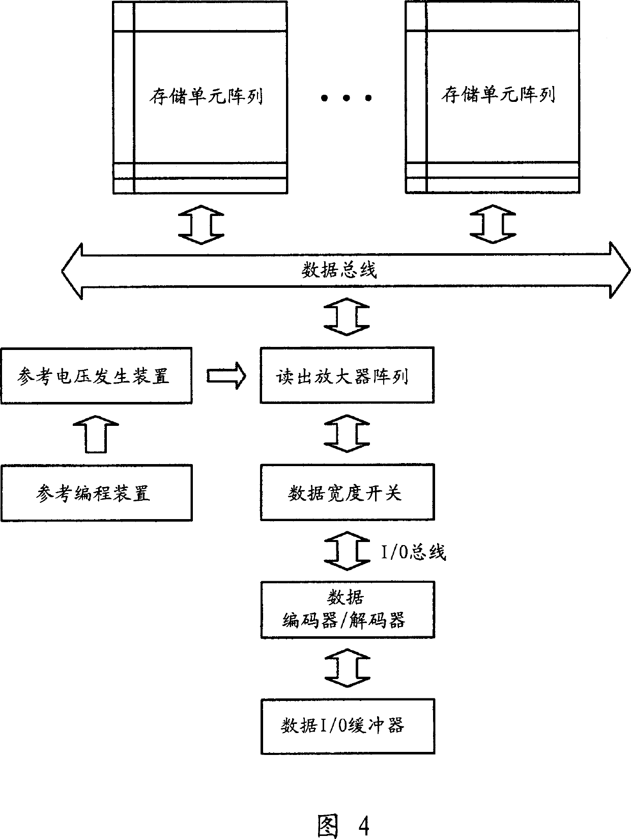
[0044] Fig. 4 is a schematic structural diagram of a ferroelectric memory device according to a preferred embodiment of the present invention.

[0045] The reference voltage generating device supplies the reference voltage to the detection amplifier. In the read mode, the sense amplifier compares the reference voltage with the voltage output from the bit line of the memory cell array, and then outputs the logic level corresponding to the memory cell data through the I / O buffer. In the write mode, the sense amplifier compares the reference voltage with the signal voltage input from the I / O buffer, and then supplies data corresponding to the signal input to the bit line of the memory cell.

[0046] FIG. 5 is a schematic diagram of the structure of the memory cell array shown in FIG. 4.

[0047] Each column of the memory cell array includes: a main bit line pull c...


PUM


Abstract

A non-volatile ferroelectric memory device is provided to output variously reference voltages by applying a programmable register device to a reference generation unit. A non-volatile ferroelectric memory device includes a reference program unit and a reference voltage generation unit. The reference program unit controls and outputs a voltage of a reference level control signal by controlling a state of a switch. The switch is used for controlling a capacitor connected to the driving power by using a programmable register device for programming a level of an output signal according to an external signal. The reference voltage generation unit outputs a reference voltage according to a reference level control signal.

Description

Technical field [0001] The present invention generally relates to ferroelectric memory devices, and more specifically to a ferroelectric memory device including a reference voltage generator and a redundant decoder. The reference voltage generator uses a programmable register to adjust the reference voltage level, and it uses an external signal to program the output signal voltage. The programming result is maintained without power supply to control the on / off of the switch. The switch adjusts the capacitance of the capacitor connected to the driving power supply. The redundant decoder uses a programmable register as the on / off of the switch Turn on the controller for programming redundant address programs. Background technique [0002] In general, ferroelectric random access memory (hereinafter referred to as "FRAM") as the memory of the next century has attracted great attention, because its processing speed is as fast as DRAM, even when the power is disc...

Claims


Application Information

Patent Timeline
IPC IPC(8): G11C11/22G11C16/02
CPCG11C11/221G11C11/2275G11C11/2297G11C29/781
Inventor 姜熙福
Owner SK HYNIX INC
Why Eureka
Try Eureka