Fuel-saving system for engine

An engine and power technology, applied in charging systems, engine components, machines/engines, etc., can solve problems such as increased fuel consumption, environmental pollution, waste, etc.

Inactive Publication Date: 2004-03-24
孙文彬
View PDF0 Cites 2 Cited by
  • Summary
  • Abstract
  • Description
  • Claims
  • Application Information

AI Technical Summary

Problems solved by technology

Another type of jet engine is as figure 2 As shown, the oil in the fuel tank is intermittently sprayed in the form of mist through the nozzle in the engine, and at the same time, the fresh air is introduced into the engine by the air filter, and the piston is driven to reciprocate after ignition and explosion However, in use, according to expert verification, only 30% of the fuel can be converted into power, a

Method used


Image

  • Fuel-saving system for engine
  • Fuel-saving system for engine
  • Fuel-saving system for engine

Examples


Embodiment 1

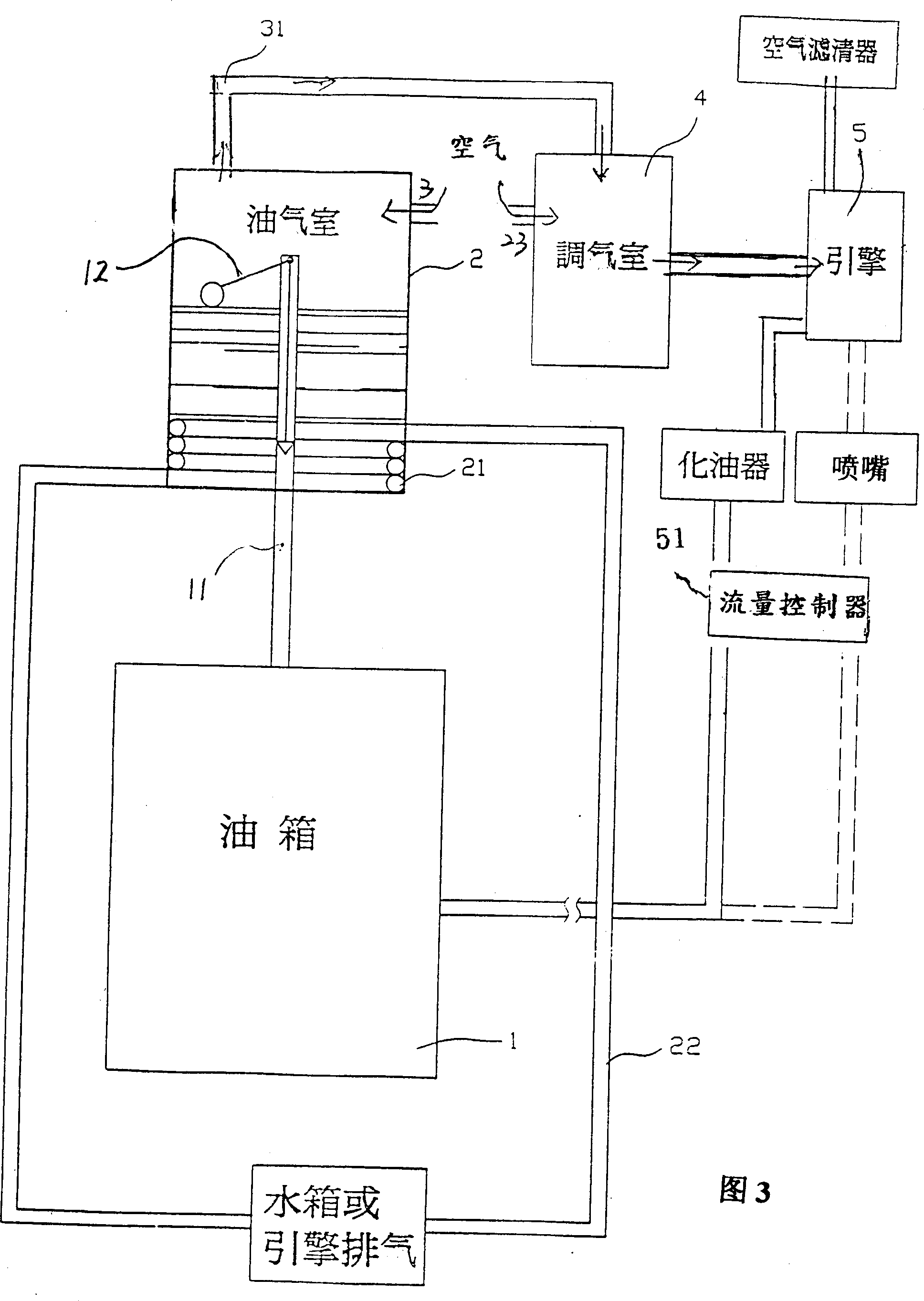
[0018] Please refer to Fig. 3, the fuel-saving system of the present invention is mainly to connect the fuel tank 1 with a fuel-gas chamber 2 through a pipeline 11 on the basis of the original fuel supply line, so that the fuel in the fuel tank 1 can be delivered to the fuel-gas chamber 2 The inner lower side of the oil-gas chamber 2 is provided with a heating pipeline 21, and the two ends of the heating pipeline 21 extend out of the oil-gas chamber 2, and are connected with the tank or engine exhaust to form a circulation loop 22, so that the high-temperature water in the water tank or The heat energy of the exhaust gas emitted by the engine flows into the heating pipeline 21 in the oil and gas chamber 2 to achieve the function of heating the inside of the oil and gas chamber 2, so that the oil and gas chamber is maintained at 60-70 degrees Celsius. At the same time, a switch is set in the pipeline 11 Valve 12, in order to control the amount of fuel oil entering the oil-gas ch...

Embodiment 2

[0020] Please refer to Fig. 4, when gasoline fuel is used, due to the high volatility of gasoline, it will volatilize quickly after heating, which will cause waste, and diesel gas can be used instead. Therefore, an independent auxiliary fuel tank 6 must be set in addition to provide oil and gas The fuel oil in chamber 2, like this, after heating, just can form the more stable oil gas of high volatilization. It is transported to the air chamber 4 by the negative pressure suction of the engine, and enters the engine 5 after desalination. At the same time, the supply of the crude oil tank is reduced to 30% to 40% of the gasoline mixed with the input engine to detonate to provide power.

Embodiment 3

[0022] For injection engines, the fuel supply is controlled by the computer, and gasoline is a highly volatile fuel, so the fuel tank 1 can be used instead of the oil and gas chamber 2 without heating the pipeline 21. The negative pressure suction of the engine is controlled by the oil and gas chamber 2. The oil vapor is transported to the gas regulating chamber 4. After desalination, it enters the engine, and then the original vehicle provides the original fuel supply, which is input into the engine to mix and provide power, which can also achieve the purpose of saving fuel and reducing air pollution.

[0023] See experimental data:

[0024] speed

[0025] speed


PUM


Abstract

The fuel-saving system of engine power machine is characterized by that it has a fuel gas chamber communicated with fuel tank, said fuel gas chamber is equipped with a heating pipeline for heating its internal high-volatile fuel and making it into high-stability fuel gas, then the fuel gas is fed into a gas-regulating chamber and mixed with exterior air, then the thined fuel gas is mixed with the fuel gas conveyed by original fuel-supplying pipeline, and fed into engine to make explosive combustion.

Description

(1) Technical field [0001] The invention relates to an oil-saving system of an engine power tool. (2) Background technology [0002] With the rapid development of my country's social economy, motor vehicles are more closely related to people's daily life. People are beginning to use vehicles as a means of transportation, and the power of the vehicles comes from the engine, and the energy for the engine comes from fuel. The power generated by the engine action is roughly divided into two systems, one of which can be found in figure 1 , the fuel is transported from the fuel tank to the carburetor to atomize the fuel, and after the air filter introduces fresh air to mix together to form oil and gas, it is then transported to the combustion chamber in the engine to ignite and explode, thereby driving the piston to reciprocate to generate power . Another type of jet engine is as figure 2 As shown, the oil in the fuel tank is intermittently sprayed in the form of mist through ...

Claims


Application Information

Patent Timeline
IPC IPC(8): F02M31/04
Inventor 孙文彬
Owner 孙文彬
Why Eureka
Try Eureka