Device for carrying out material exchange processes
A material exchange and equipment technology, applied in the field of equipment implementing the material exchange method, can solve the problem of not mentioning the polymer solution, etc., and achieve the effect of uniform product distribution
- Summary
- Abstract
- Description
- Claims
- Application Information
AI Technical Summary
Problems solved by technology
Method used
Image

Examples
example 1
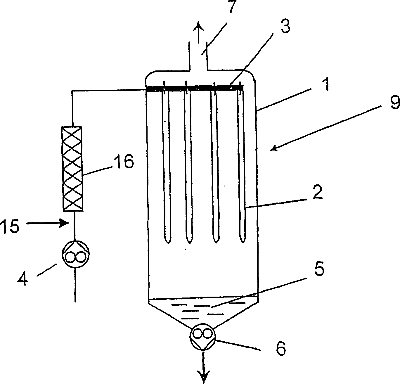
[0056] according to figure 1 , in a vertically placed degassing container 1, there are four wire loops 2 extending in the vertical direction. The wire loop 2 is fastened to a horizontally extending and here tubular distribution element 3 . The distribution part 3 is connected to a supply device 4 . The degassed product is removed at the sump 5 of the container 1 by means of a gear pump 6 . The residual steam generated during degassing is discharged through the pipe joint 7. Via the pipe connection 7 a predetermined reduced pressure can be set in the container 1 . The container 1 can be heated by an electric heating device (not shown).
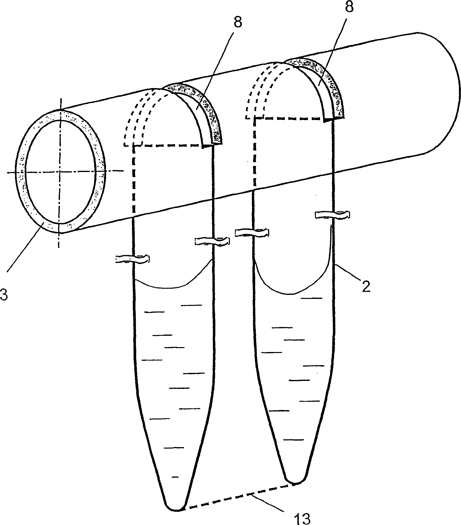
[0057] figure 2 Indicates how the wire loop 2 is fixed on the distribution pipe 3. They are hung on the slot-shaped opening 8 arranged on the upper part of the distribution pipe 3 in such a way that the slot-shaped opening 8 extends longitudinally over the entire width of the wire loop, so that the wire loop receives the liquid product t...
example 2
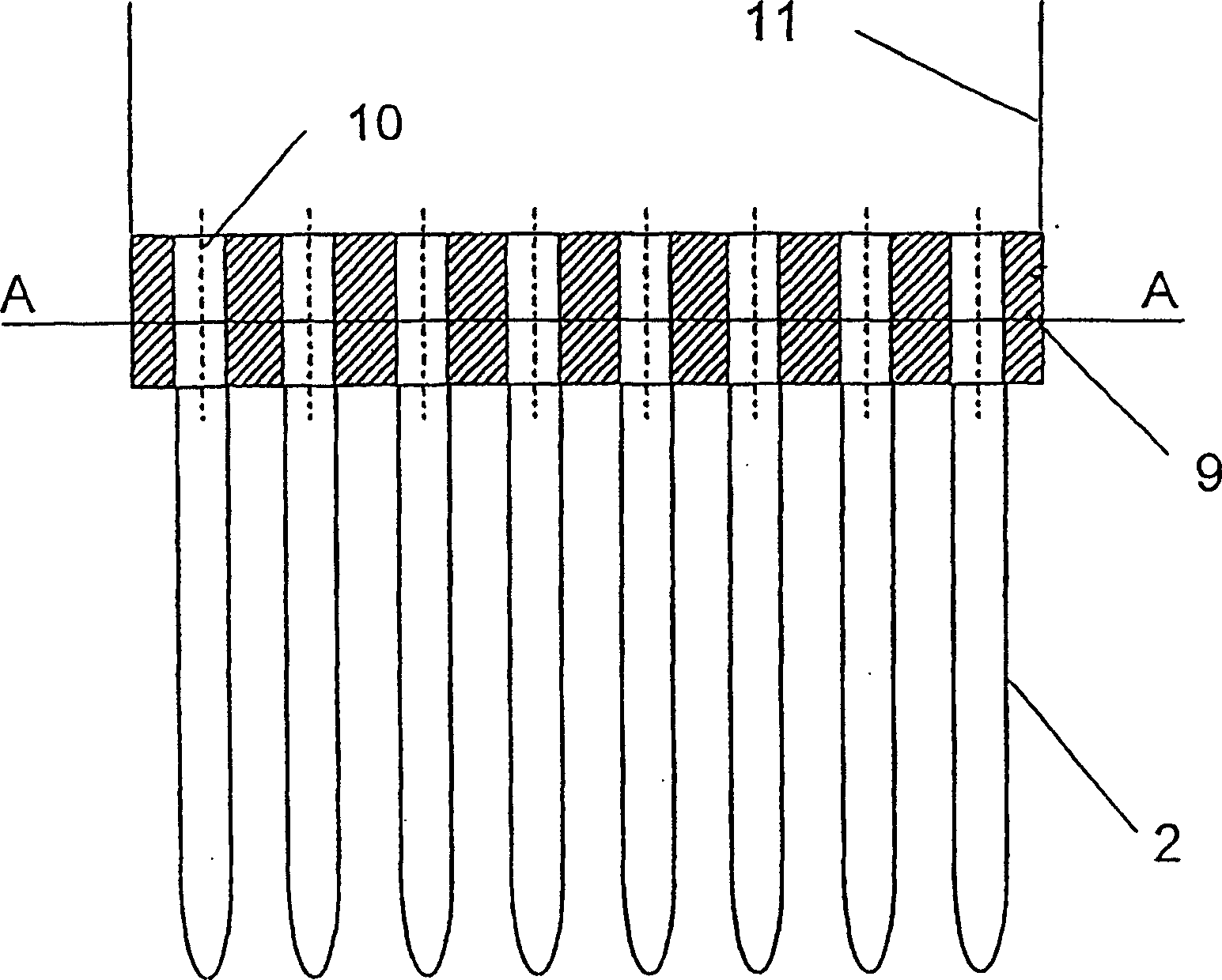
[0059] In another evaporator configuration (top view and side view) as shown in FIG. 3 , the distribution element for feeding the liquid product consists of a nozzle plate 9 with openings 10 . The wire loop 2 is fastened, such as soldered or welded, on the underside of the nozzle plate 9 . The liquid product is supplied via a supply line 11 covering the entire cross section of the nozzle plate 9 . The inlet pipe 11 can also be designed in the form of a heat exchange pipe.
example 3
[0061] The distributing elements described in examples 1 and 2 can also be designed in this way. As shown in FIGS. 4 and 5 , the liquid product is sent to the wire loop 12 through the heat exchange tubes 12 arranged vertically in the container 1 . In the embodiment shown in FIG. 4 , the wire loops 12 are placed respectively on the outlets of the heat exchange tubes 12 , ie in this case the heat exchange tubes directly serve as supports for the wire loops 2 . In order to be more stable, at its bottom end, the wire loops 2 are connected by horizontal bars 13 to form a grid (see top view). On the contrary, in the modified embodiment shown in FIG. 5 , the wire rings 2 are respectively arranged on two adjacent heat exchange tubes 12 , so that liquid is supplied into the wire rings 2 through two liquid input mechanisms respectively. In this embodiment, the ends of the tapered loops are connected by crossbars 13 .
[0062] In all the above examples the wire loop 2 is bent from a 1....
PUM
| Property | Measurement | Unit |
|---|---|---|
| Area | aaaaa | aaaaa |
Abstract
Description
Claims
Application Information
 - R&D
- Intellectual Property
- Life Sciences
- Materials
- Tech Scout
- Unparalleled Data Quality
- Higher Quality Content
- 60% Fewer Hallucinations
Browse by: Latest US Patents, China's latest patents, Technical Efficacy Thesaurus, Application Domain, Technology Topic, Popular Technical Reports.
© 2025 PatSnap. All rights reserved.Legal|Privacy policy|Modern Slavery Act Transparency Statement|Sitemap|About US| Contact US: help@patsnap.com