X-ray tube with ring anode and its application

A technology of X-ray tube and annular anode, which is applied in the field of X-ray tubes and can solve problems such as expensive structure, large size and complexity

Inactive Publication Date: 2004-04-07
SIEMENS AG
View PDF4 Cites 9 Cited by
  • Summary
  • Abstract
  • Description
  • Claims
  • Application Information

AI Technical Summary

Problems solved by technology

Such a cathode ray tomography camera, although it does not require mechanically moving parts and can be directly cooled, has a complex, bulky and expensive construction, and is therefore only rarely used in practice

Method used


Image

  • X-ray tube with ring anode and its application
  • X-ray tube with ring anode and its application
  • X-ray tube with ring anode and its application

Examples


Embodiment Construction

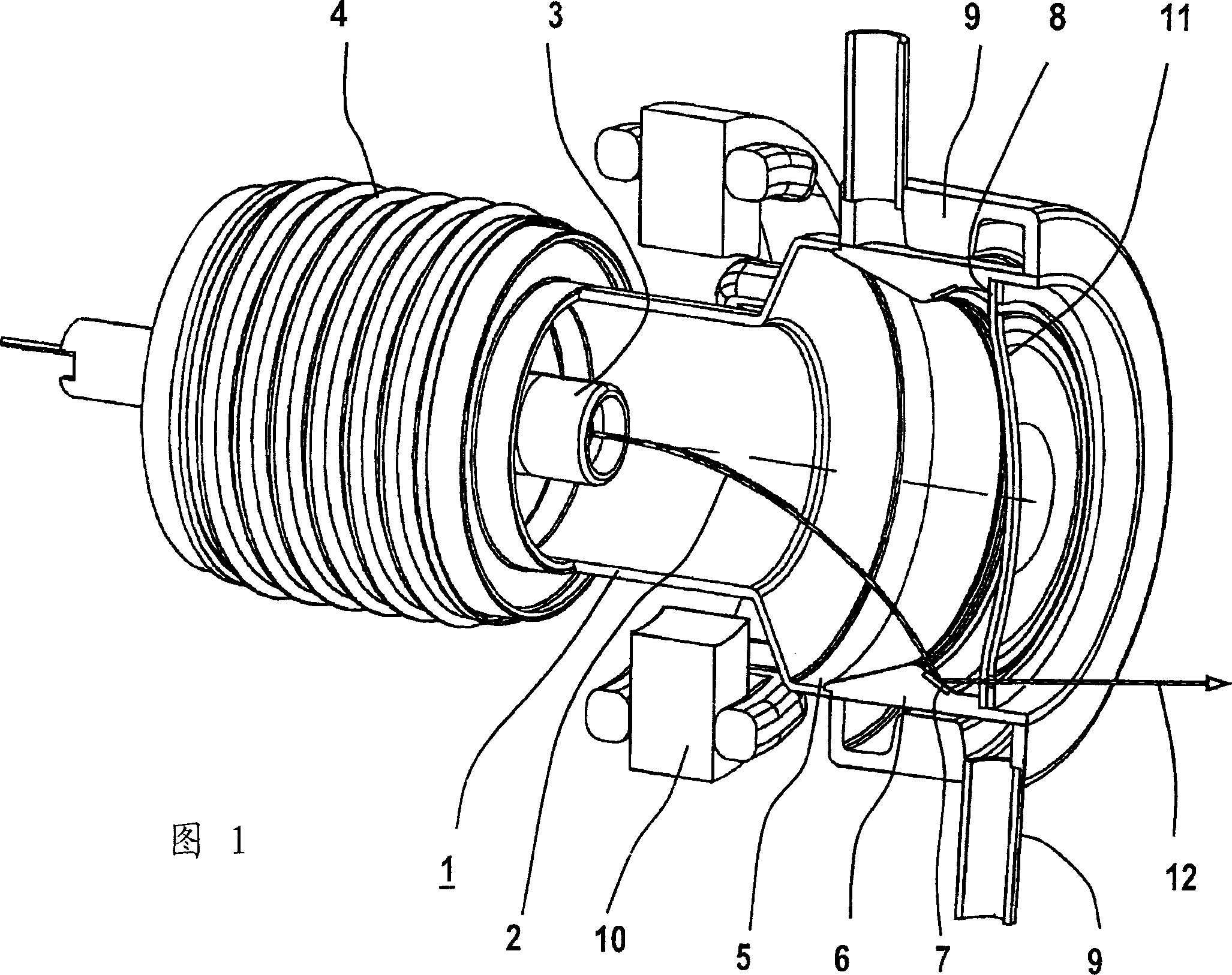
[0026] FIG. 1 shows the x-ray tube according to the invention with a vacuum housing 1 in which a cathode 3 with a circular emitter for generating an electron beam 2 is located.

[0027] The cathode 3 is connected to an annular anode 6 via an insulator 4 and a widened tube section 5 . The inwardly directed surface of the ring-shaped anode 6 has an essentially triangular cross-section consisting of a long side and a short side, the long side facing the cathode 3 . An impact surface 7 is provided for the electron beam 2 on the short side.

[0028] A radiation exit window 8 through which x-rays pass is arranged in front of the annular anode 6 and forms the front cover of the x-ray tube. An anode cooling system 9 is arranged around the ring-shaped anode 6 , which has an inlet and an outlet and channels for the flow of cooling fluid and is thermally conductive, in particular in the region of the impingement surface 7 , with the The ring anode 6 is connected. In the area of ​​the ...


PUM


Abstract

An X-ray tube has a stationary vacuum housing (1), in which are arranged an electron-emitting cathode (3) and a ring anode (4) with an impact surface (7, 22) on which the electron beam (2), accelerated by an electrical field, is incident, as well as a deflection system to focus and deflect the electron beam (2). The ray exit window (8) of the X-ray tube is round, lies in the plane perpendicular to the central axis of the X-ray tube, and terminates one side at the vacuum housing (1). The impact surface (7, 22) of the ring anode (4) is beveled and is aligned to the ray exit window (8). A diaphragm (11) is provided in front of the ray exit window (8) that defines a circular opening for the X-ray radiation (12, 13). The ring anode (4) is surrounded by an annular anode cooling arrangement (9).

Description

technical field [0001] The invention relates to an x-ray tube with a stationary vacuum housing and a deflection system. Such X-ray tubes are well known and generate X-rays for examining an object to be inspected. Background technique [0002] Commonly used X-ray tubes have a fixed anode. In medical technology at higher powers, the focus of an x-ray tube is formed on a focus track by rotating the anode by means of an electromechanical drive, thereby distributing the thermal load over a large area. At the same time, heat is stored via a graphite disc. However, X-ray tubes of this type require an expensive mounting for the anode due to the high rotational kinetic energy required by the anode and the relatively high weight in the case of graphite discs. Cooling of the anode is also generally not possible directly. Achieving direct cooling is extremely complex. [0003] But for example from US patent US 6,292,538 B1 so-called rotating cylindrical tubes are known, in which th...

Claims


Application Information

Patent Timeline
Patent Type & Authority Applications(China)
IPC IPC(8): H01J35/08H01J35/30
CPCH01J35/30H01J35/08H01J35/13
Inventor 曼弗雷德·阿佩尔霍尔格·鲍尔弗兰克·诺伊曼
Owner SIEMENS AG
Why Eureka
Try Eureka