Motor control system and method

A motor control and drive motor technology, applied in the control system, vector control system, motor generator control, etc., can solve problems such as compressor vibration or noise compressor performance degradation

Inactive Publication Date: 2004-04-14
LG ELECTRONICS INC
View PDF0 Cites 14 Cited by
  • Summary
  • Abstract
  • Description
  • Claims
  • Application Information

AI Technical Summary

Problems solved by technology

More specifically, a pulsation of 60 to 100 rpm occurs due to simultaneous compression and expansion strokes when driving the blades of the compressor. Figure 2b plots the speed characteristics of the motor on the time axis, showing this pulsation, these pulsations Causes unwanted compressor vibration or noise and compressor performance degradation

Method used


Image

  • Motor control system and method
  • Motor control system and method
  • Motor control system and method

Examples


Embodiment Construction

[0016] best practice

[0017] Now, preferred embodiments of the present invention will be described with reference to the accompanying drawings.

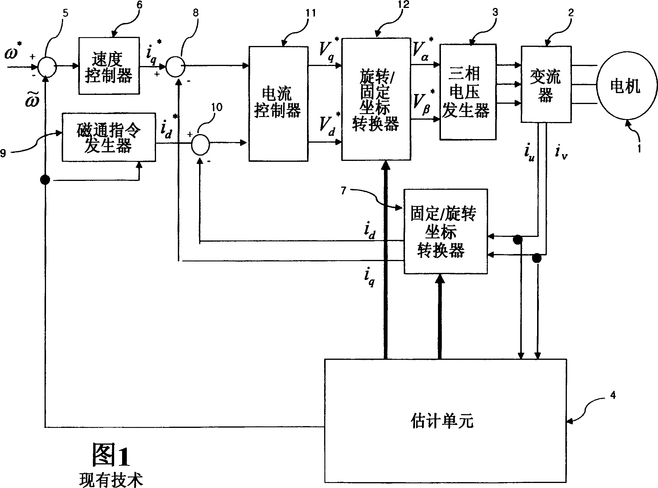
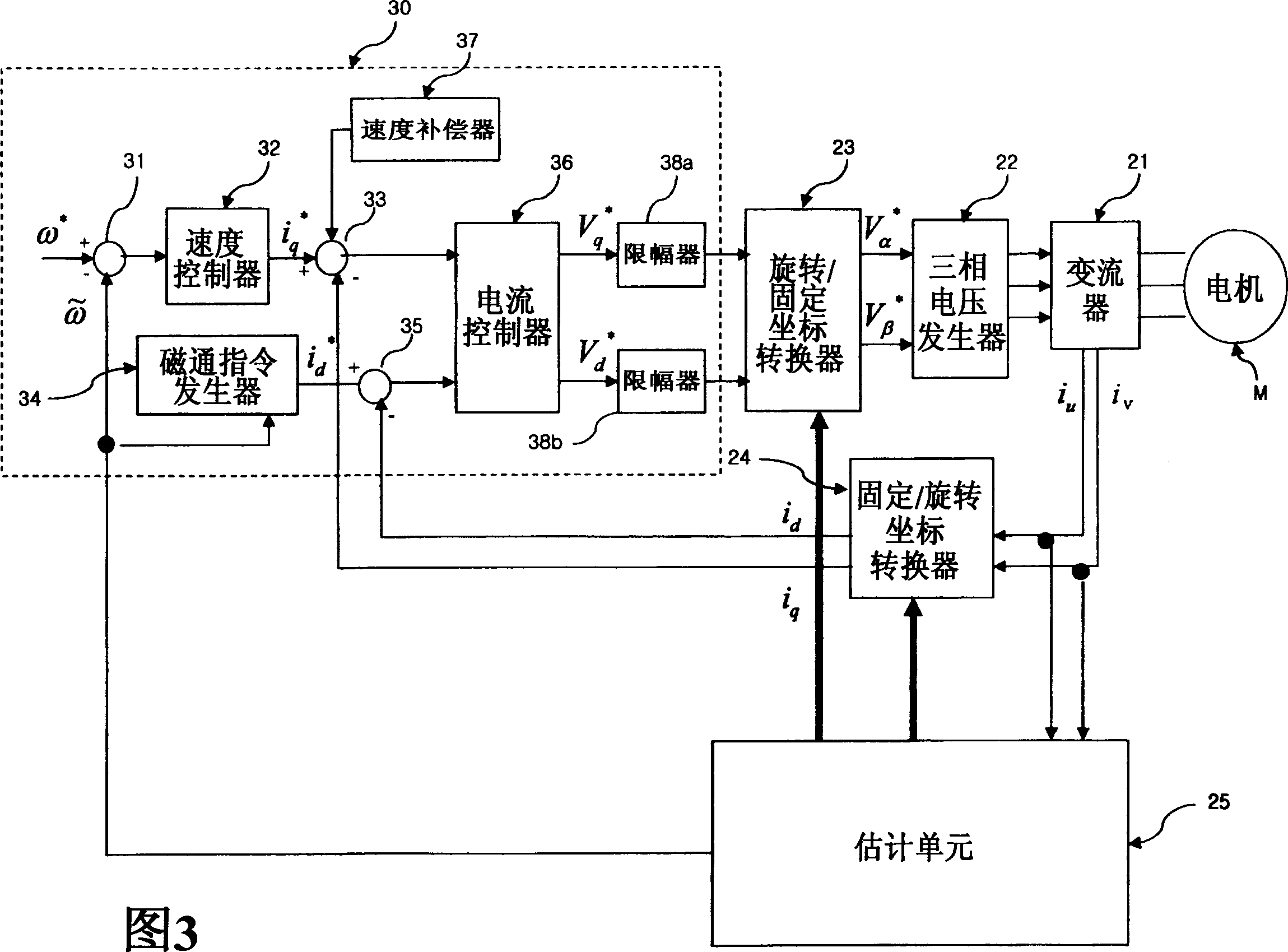
[0018] Fig. 3 is a block diagram of a motor control system according to a preferred embodiment of the present invention. Referring to FIG. 3, the control system of the motor M includes: a three-phase voltage generator 22 for applying three-phase voltages to the converter 21 so that the converter 21 can drive the motor M according to a control signal from a microcomputer (not shown). ; The rotating / fixed coordinate converter 23 is used to convert the reference magnetic flux voltage V of the rotating coordinate system of the motor M d * and reference torque voltage V q * Converted to the flux voltage V of the fixed coordinate system α * and torque voltage V β * , and the flux voltage V α * and torque voltage V β * output to a three-phase voltage generator 22; and a fixed / rotary coordinate converter 24 for converting the th...


PUM


Abstract

The present invention relates to a system and a method for controlling a motor. A rotation/fixed coordinates converter converts a reference magnetic flux voltage and a reference torque voltage of a rotation coordinates system into data of a fixed coordinates system, and outputs the data to the three-phase voltage generator. A fixed/rotation coordinates converter converts a three-phase current applied from the inverter to the motor into a two-phase current. An estimation unit estimates a rotation angle and rotor speed of the motor upon receiving currents applied to the fixed/rotation coordinates converter. A control block receives the estimated rotation angle and the estimated speed from the estimation unit, and outputs the reference magnetic flux voltage and the reference torque voltage of the motor to the rotation/fixed coordinates converter to compensate an error caused by loads generated when driving the motor. Thus, the control system greatly reduces noise and vibrations of a compressor without being affected by loads generated by compression/expansion strokes of the compressor at a startup time of the motor, and prevents a performance of the compressor from being deteriorated.

Description

technical field [0001] The present invention relates to a system for controlling a motor, in particular, to a system for controlling a motor for eliminating speed pulsation generated when controlling the motor and noise generated when driving the motor, wherein the speed pulsation is caused by It is caused by the load generated when driving the single-screw compressor. Background technique [0002] Generally, in order to control a motor, a motor control system is required to recognize speed information or flux information of the motor. Existing motor control systems are equipped with speed sensors, such as resolvers or pulse encoders, or magnetic flux sensors to identify speed information and magnetic flux information, but these sensors are difficult to install and are greatly affected by the installation environment, so it is inevitable Increased manufacturing costs. [0003] Therefore, various motor speed control systems that do not use speed sensors and flux sensors hav...

Claims


Application Information

Patent Timeline
Patent Type & Authority Applications(China)
IPC IPC(8): F04C28/08F04B49/06H02P21/00H02P21/05H02P21/14H02P21/18H02P21/22H02P21/24H02P23/04H02P23/16H02P27/04
CPCH02P21/146H02P21/0042H02P25/08H02P21/05H02P21/18H02P21/26H02P21/00
Inventor 郑达浩元俟喜吴在胤李炅勋
Owner LG ELECTRONICS INC
Why Eureka
Try Eureka