Vacuum casting appts.

A vacuum and vacuum technology, applied in foundry workshops, foundry equipment, manufacturing tools, etc., can solve the problems of rust stains, low device operation efficiency, high cost, etc.

Active Publication Date: 2004-05-26
ULVAC INC
View PDF3 Cites 6 Cited by
  • Summary
  • Abstract
  • Description
  • Claims
  • Application Information

AI Technical Summary

Problems solved by technology

[0008] The vacuum melting and casting device cited in Patent Document 1 should open the vacuum chamber to the atmosphere every time casting, take out the recovery tray, and if necessary, use The vacuum chamber reaches the predetermined vacuum degree again, and melting and casting are restarted. However, due to the time in which the vacuum chamber is in the atmosphere and the start of vacuum exhaust, the casting has to be interrupted until the predetermined vacuum degree is reached, which leads to the operation efficiency of the device. low
Also, since the melting furnace is in contact with the atmosphere, the attached metal on the inner wall is prone to oxidation and rust stains
[0009] The above-mentioned problems of Patent Document 1 do not exist in the vacuum melting and casting device of Patent Document 2, but, in order to improve operating efficiency, preparation chambers are provided on both sides of the melting chamber. The overall size of the device will be increased by preparing a plurality of moving carts equipped with tundishes and cooling rolls. Furthermore, since the moving carts move between the atmosphere, the preparation room, and the melting and casting room, productivity and workability will be improved. Good, but expensive to install
[0010] In the ingot casting device of Patent Document 3, in addition to cooling the molten steel in the mold, it takes time for cooling. In order to take out the steel ingot formed in the mold, the casting chamber must be opened to the atmosphere, so it cannot be carried out during this period. Casting, with which the melting process in the melting chamber is also interrupted, thus resulting in inefficient operation of the plant

Method used


Image

  • Vacuum casting appts.
  • Vacuum casting appts.
  • Vacuum casting appts.

Examples


Embodiment Construction

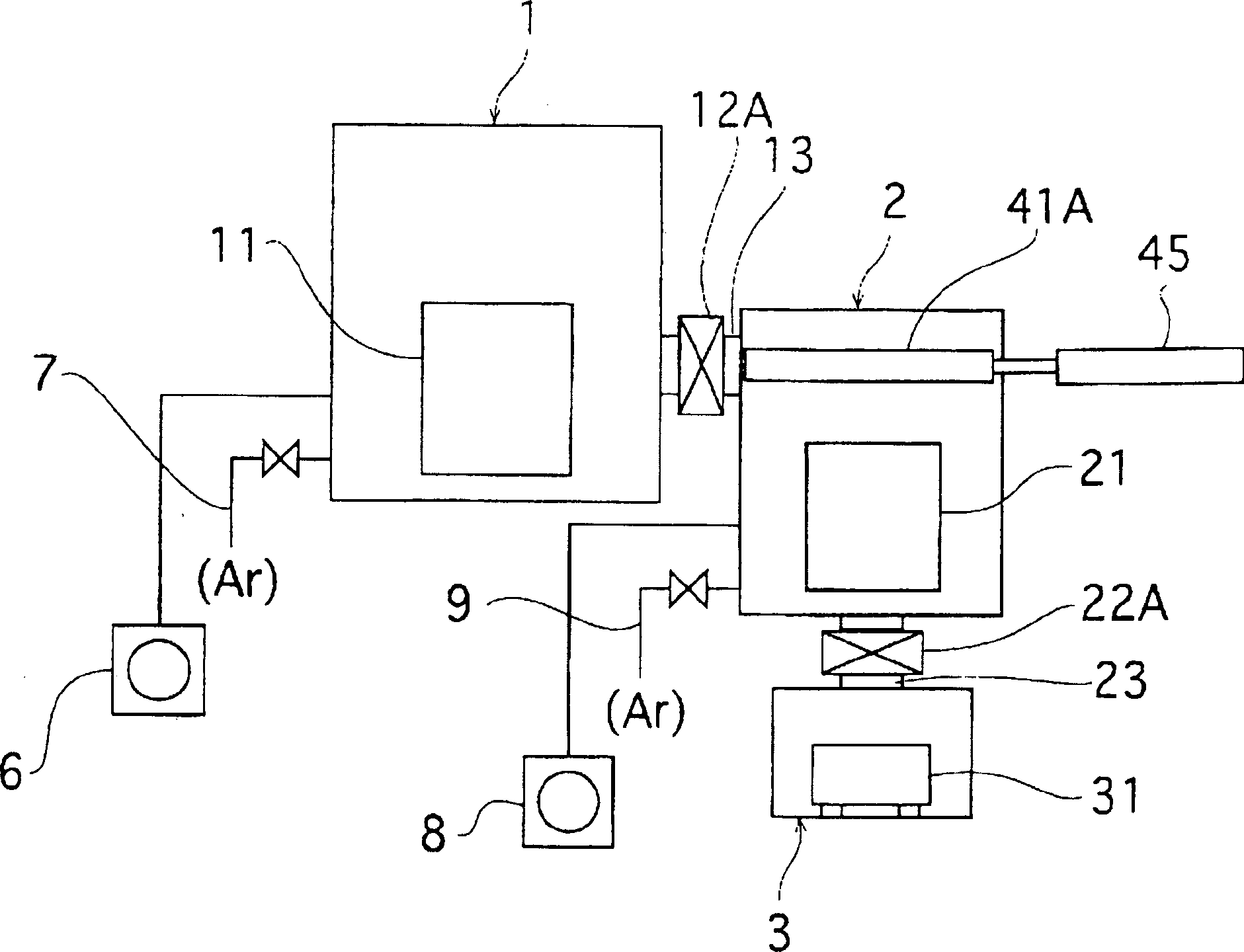
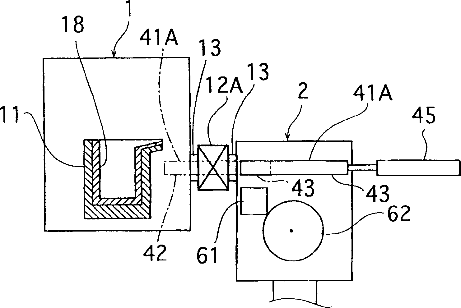
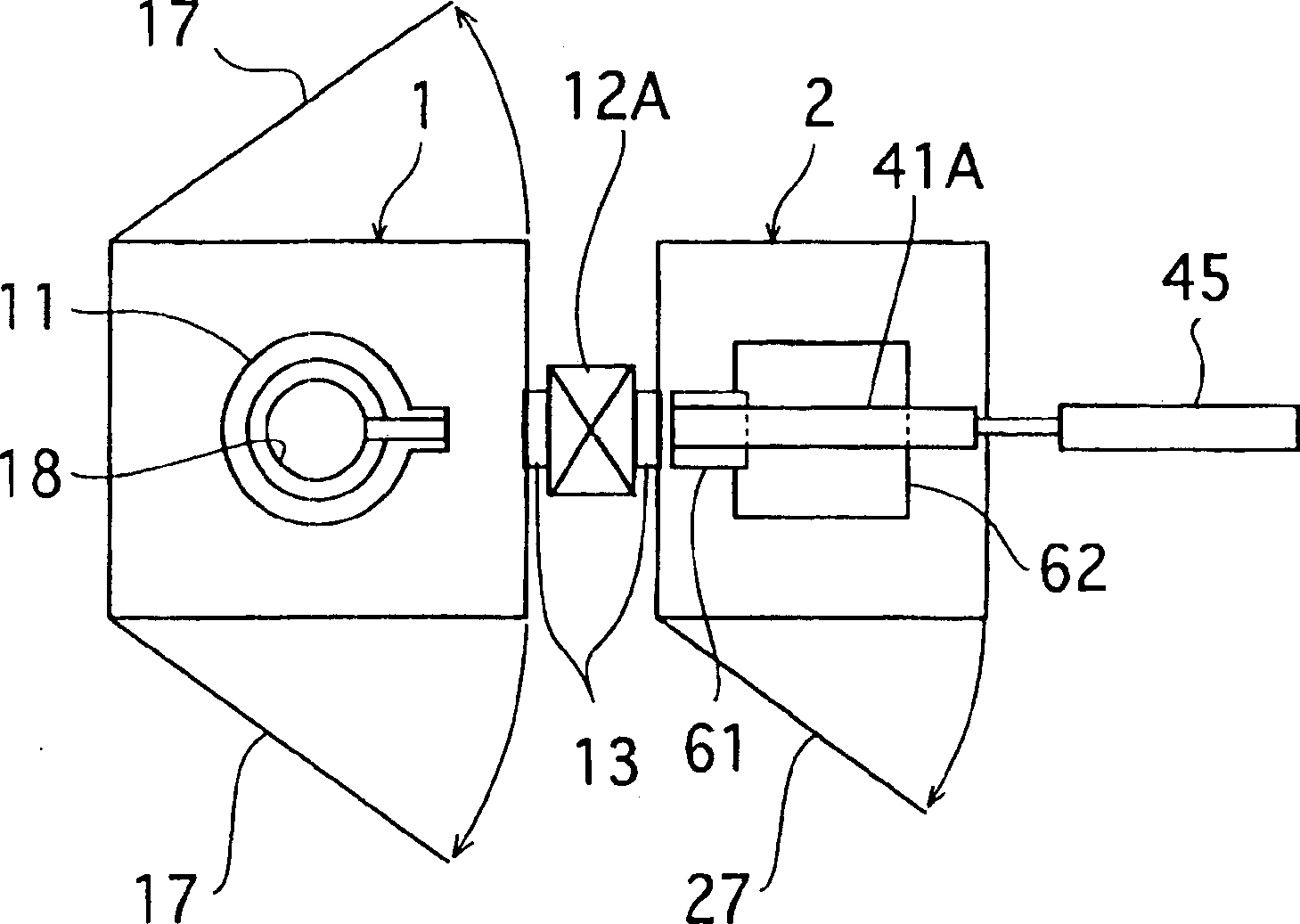
[0059] As described above, the vacuum melting and casting apparatus of the present invention includes a melting furnace that melts an alloy containing rare earth elements under vacuum or an inert gas atmosphere, and a casting apparatus that cools and casts the molten metal of the alloy. The melting chamber of the furnace and the casting chamber with the casting device are formed, and the melting chamber and the casting chamber are vacuum-sealed through the first partition mechanism or the first sealing mechanism provided with the first partition mechanism regardless of the vacuum degree of the two. The vacuum melting and casting device may also include a melting furnace for melting alloys containing rare earth elements under vacuum or an inert gas atmosphere, a casting device for cooling and casting molten metal of alloys, and a recovery of castings formed by receiving and outputting The vacuum melting and casting device is composed of a melting chamber with a melting furnace, ...


PUM


Abstract

To provide a vacuum melting and casting apparatus, which can improve its availability factor by making the apparatus compact and by increasing the number of cycles of melting and casting, and further can cope with a variety of requirements by selecting each process of melting, casting, and collecting of castings among a plurality of processes. The apparatus is divided into a melting chamber 1, a casting chamber 2, and a collecting camber 3, and the volumes of the respective chambers are reduced. The melting chamber 1 and the casting chamber 2 are connected via a first closed passage 13 having a first gate valve 12, which can be vacuum-sealed even when a degree of vacuum in any chamber is high. A flap valve 99, which opens and closes the end portion of the downstream side of a second closed passage 23 in the collecting chamber 3, is provided between the casting chamber 2 and the collecting chamber 3. When the molten metal is to be poured, the opened first gate valve 12 and the first closed passage 13 are advanced, and the molten metal is poured from a melting furnace 11 of the melting chamber 1 into a rectangular pipe shape rounder 41 provided to pour the molten metal to a tundish 61 of the casting chamber 2. When the molten metal is not to be poured, the first gate valve 12 and the first closed passage 13 are retracted, and then the first gate valve 12 is closed. (C)2004,JPO.

Description

technical field [0001] The present invention relates to a vacuum melting and casting device for alloys containing rare earth elements, more specifically, the present invention relates to a melting chamber having a melting furnace separated from a casting chamber having a casting device and a recovery chamber having a cast product recovery container , and a vacuum melting and casting device connected to each other through a partition mechanism. Background technique [0002] Vacuum casting apparatuses for alloys containing rare earth elements represented by, for example, samarium-cobalt alloys and neodymium-iron-boron alloys have been proposed previously. One example is equipped with a melting furnace, a tundish, a cooling roll and a recycling tray for castings that can be tilted in the vacuum chamber. The melting furnace and the cooling roller are fixed, and the tundish can move sideways in the vacuum chamber. It can be taken out from the vacuum chamber (see, for example, Ja...

Claims


Application Information

Patent Timeline
Patent Type & Authority Applications(China)
IPC IPC(8): B22D11/06B22D13/04B22D21/02B22D23/00B22D45/00B22D47/00B22D47/02
Inventor 向江一郎吉泉良加藤丈夫
Owner ULVAC INC
Why Eureka
Try Eureka