Aluminum electrolytic condenser

A technology of aluminum electrolytic capacitors and capacitor cores, applied in electrolytic capacitors, solid electrolytic capacitors, capacitors, etc., can solve the problems of current capacity heating, inability to flow current, and heat generation, and achieve strong noise absorption, less heat generation, and reduced heat generation. The effect of small resistance

Inactive Publication Date: 2004-05-26
FUJITSU MEDIA DEVICES
View PDF0 Cites 19 Cited by
  • Summary
  • Abstract
  • Description
  • Claims
  • Application Information

AI Technical Summary

Problems solved by technology

[0015] However, in a two-terminal structure in which the anode-side lead terminal from the anode and the cathode-side lead terminal from the cathode are each one, as in Figure 16 As shown in the part surrounded by double dotted lines, the equivalent circuit is to arrange ESR and ESL in series, so the resistance of the lead terminal and the contact resistance between the energizing foil and the lead terminal make the impedance and ESR (equivalent series resistance) have a certain relationship. limit
In addition, due to the L (inductance) amount of the lead terminal, there is a limit to reducing the ESL (equivalent series inductance)
[0016] In addition, when the conventional two-terminal structure is used in a high-frequency application circuit through which a large current flows, there is a problem that the current capacity of the lead terminal and the resistance of the connecting portion between the lead terminal and the electrode foil cause heat generation. , so no large current can flow
[0018] Furthermore, when an aluminum electrolytic capacitor is used in a high-frequency application circuit in which a large current flows, a large current cannot flow due to heat generated by the current capacity of the lead terminal and the resistance of the connecting portion between the lead terminal and the electrode foil. electric current

Method used


Image

  • Aluminum electrolytic condenser
  • Aluminum electrolytic condenser
  • Aluminum electrolytic condenser

Examples


Embodiment Construction

[0047] Hereinafter, the best mode for carrying out the present invention will be described in detail with reference to the accompanying drawings.

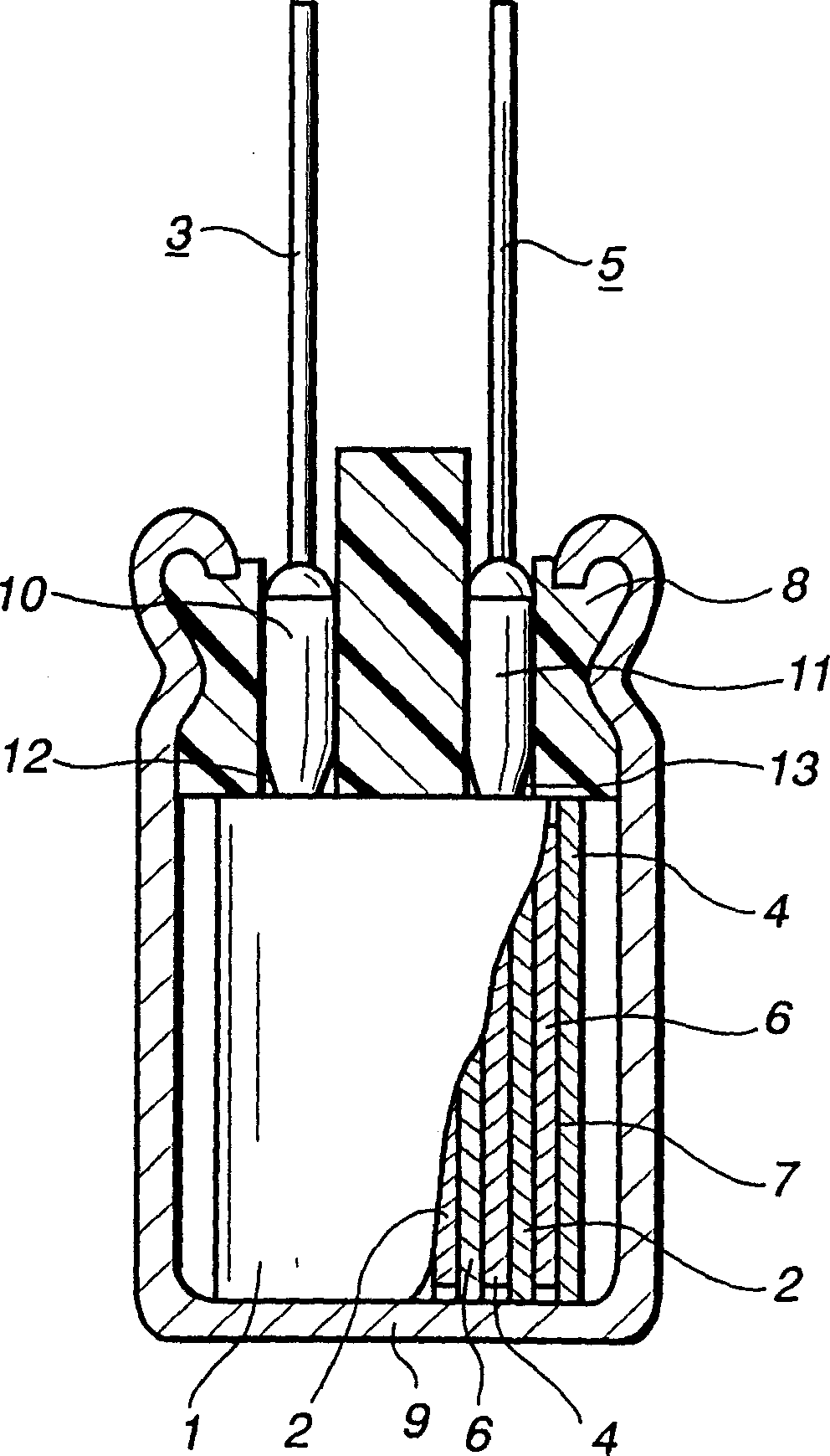
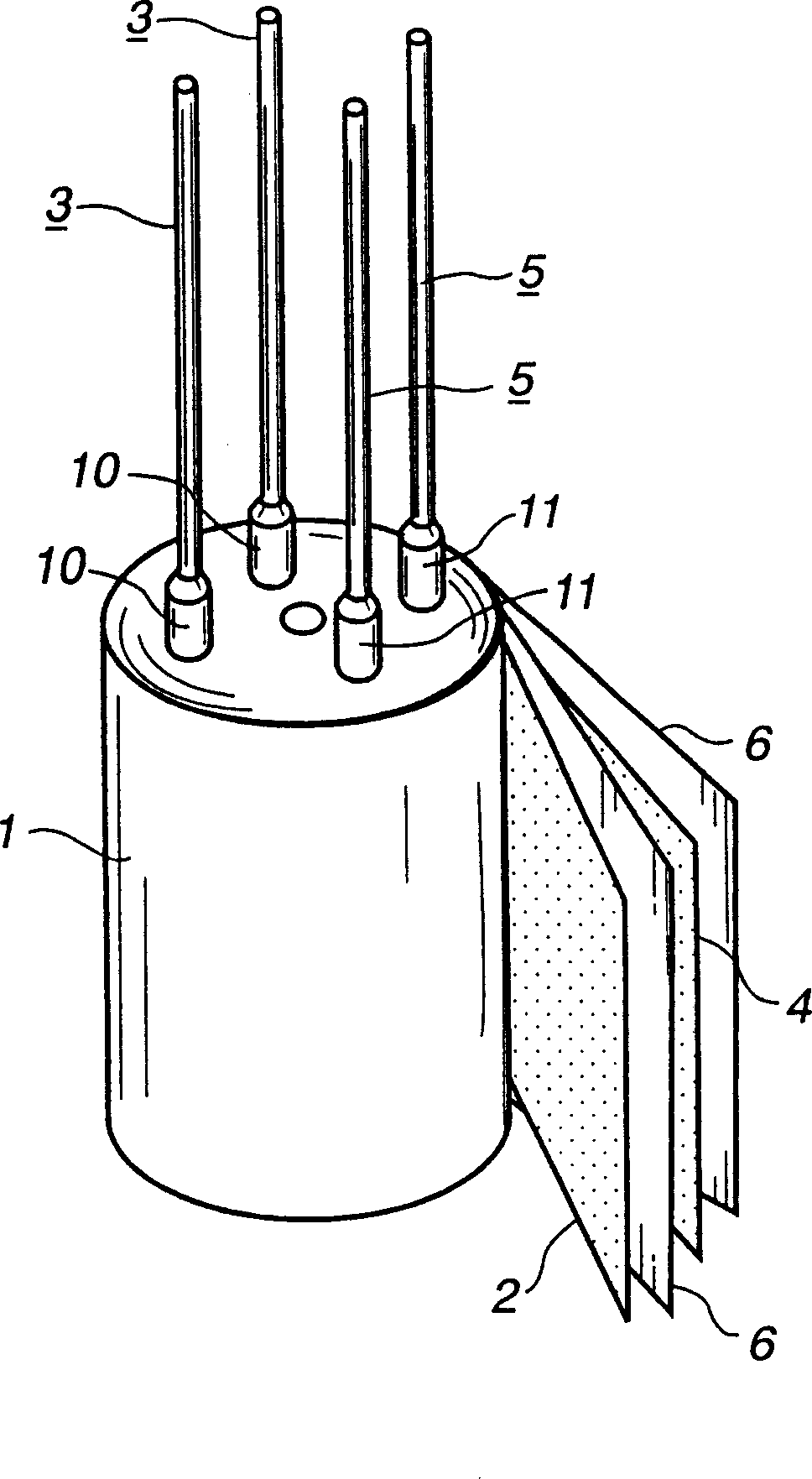
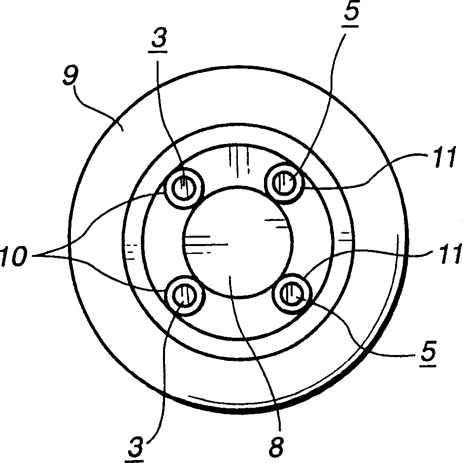
[0048] exist figure 1 , figure 2 and image 3 Among them, the wound solid electrolytic capacitor is composed of a capacitor core 1 , a solid electrolyte layer 7 , a sealing body rubber 8 and a case 9 .

[0049] The capacitor core body 1 formed with the solid electrolyte layer 7 and the sealing body rubber 8 are put into the casing 9 for sealing, and together with the casing 9, the sealing body rubber 8 is laterally shrunk and crimped, and then sealed to make a solid Electrolytic capacitors.

[0050] In this solid electrolytic capacitor, the electrolyte of the solid electrolyte layer 7 includes polypyrrole, polythiophene, polyaniline, etc., but in order to reduce ESR (equivalent series resistance), polyethylenedihydroxythiophene, which has a small intrinsic resistance, is mainly used.

[0051] This will now be described in more...


PUM


Abstract

Provided is an aluminum electrolytic capacitor with reduced ESR (equivalent series resistance) and ESL (equivalent series inductance). In an aluminum electrolytic capacitor including a capacitor element 1 having an anode side lead terminal 3 for anode lead-out and a cathode side lead terminal 5 for cathode lead-out, a bottomed exterior case 9 in which the capacitor element 1 is stored, and a seal rubber 8 sealing the opening part of the bottomed exterior case 9, there is a terminal structure having the selected number of the anode side and cathode side lead terminals 3 and 5 from the range within 2 to 4, respectively. By this plural terminal structure, there is a circuit in which ESR and ESL are equivalently arranged in parallel. Thereby, the resistance of the lead terminal that is the ESR component and the connection resistance between foil and the lead terminal are eliminated, so the ESR can be reduced. Moreover, the influence of inductance of the lead terminal can be removed, so the ESL can be reduced.

Description

technical field [0001] The present invention relates to an aluminum electrolytic capacitor including a vertical type capable of surface mounting, and more particularly, to an aluminum electrolytic capacitor with reduced ESR (equivalent series resistance) and ESL (equivalent series inductance). Background technique [0002] In recent years, circuits have been required to be miniaturized and adaptable to high frequencies, and therefore capacitors are also required to have low impedance. Especially for computer CPU drive circuits and switching power supply circuits, the circuit design requires absorption of high-frequency noise and ripple current, and it is particularly urgent to achieve low ESR (equivalent series resistance) and low ESL (equivalent series resistance). series inductance) capacitors. [0003] Among the conventional aluminum electrolytic capacitors, for example, the basic structure of a wound solid electrolytic capacitor is the same as that of the wound solid el...

Claims


Application Information

Patent Timeline
Patent Type & Authority Applications(China)
IPC IPC(8): H01G9/035H01G9/00H01G9/008H01G9/012H01G9/022H01G9/028H01G9/042H01G9/08H01G9/10H01G9/14H01G9/15
CPCH01G9/008H01G9/151H01G9/08H01G9/10
Inventor 小泉政义间部顺吉小泽丰山田胜治
Owner FUJITSU MEDIA DEVICES
Why Eureka
Try Eureka