Structure for installing magnetic core winding on service

A magnetic core and component technology, which is applied in the direction of inductors with magnetic cores, transformer/inductor coils/windings/connections, electrical components assembled printed circuits, etc., can solve the problem of increased manufacturing time and complexity, and the inability to obtain the lowest impedance , cost rise and other issues, to achieve the effect of cost reduction, small magnetic leakage, and hard structure

Inactive Publication Date: 2004-05-26
雅达国际有限公司
View PDF0 Cites 8 Cited by
  • Summary
  • Abstract
  • Description
  • Claims
  • Application Information

AI Technical Summary

Problems solved by technology

As a result, these prior art structures and methods drive up cost due to the increased manufacturing time and complexity n...

Method used


Image

  • Structure for installing magnetic core winding on service
  • Structure for installing magnetic core winding on service
  • Structure for installing magnetic core winding on service

Examples


Embodiment Construction

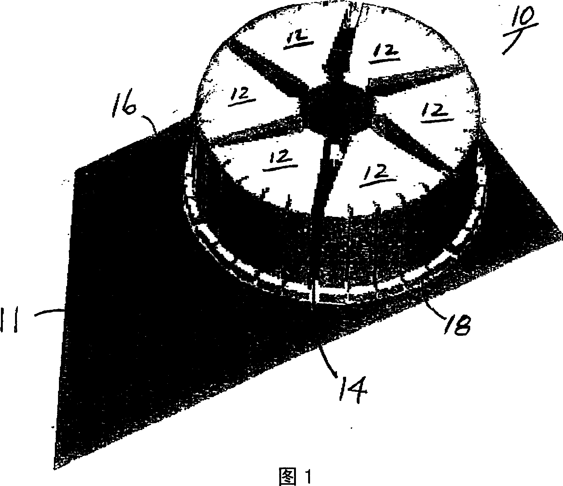
[0034] Hereinafter, the present invention will be described in detail with reference to the accompanying drawings. Figure 1 is a perspective view of an assembly 10 according to the invention formed on a surface 11 of a printed circuit board 16 or the like. As shown in FIG. 1 , assembly 10 has a surface mount magnetic core winding structure 18 attached to surface 11 . Structure 18 has a plurality of generally sector-shaped wires 12 encircling magnetic core 14 . The wire 12 forms the top half of the full turn of the coil winding, while the surface 11 ( figure 2 The traces shown in ) form the bottom half turn of each coil. Each segment wire 12 is used for each winding loop.

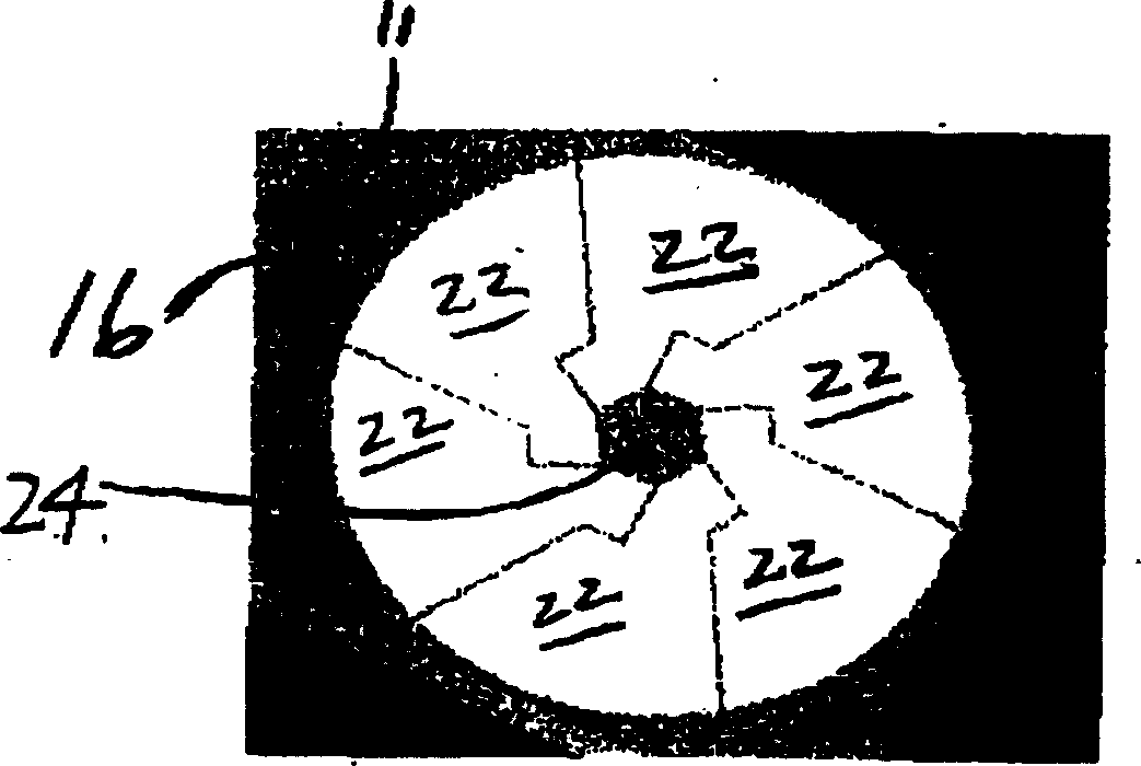
[0035] figure 2 The printed circuit board traces according to the preferred embodiment of the present invention are illustrated prior to the winding structure 18 being surface mounted thereon. Such as figure 2 As shown, printed circuit board 16 has surface 11 with a plurality of traces 22 thereon. sti...


PUM


Abstract

Conducting wire with deviated structure is fixed on pattern trace formed on printed circuit board. The wire encircles single magnetic core on surface of the printed circuit board so as to form an inductor. Shaped conducting wire can be soldered onto the designated position in procedure of back flow manufacture of whole printed circuit. Thus, annular conducting wire is provided in the gross so that it is suitable to automatic production. The said method and structure reduces parts and manufacturing cost. Small shaped inductor installed on surface is produced. Comparing with current magnetic core winding, the invention is able to reduce flux leakage.

Description

technical field [0001] The present invention relates generally to surface mount inductors, and more particularly to methods and corresponding structures including wires shaped to encircle a magnetic core to form, with traces on a printed circuit board, the windings of the inductor. The leads are also suitable for efficient positioning and soldering on printed circuit boards using automated equipment. Background technique [0002] A typical core winding configuration for an inductor generally includes a ferrite core wound with wire, and a stem or bobbin is used to hold the wire and ferrite core in the desired position. The trend in modern technology is higher density and smaller form factor electrical equipment. A common disadvantage of known core winding structures and methods with stems or bobbins is that these structures have a great height and are therefore not suitable for small profile applications, such as for mounting on a printed circuit board (PCB). inductor. [...

Claims


Application Information

Patent Timeline
IPC IPC(8): H01F17/00H01F17/06H01F27/28H01F27/32H01F41/00H05K1/16H05K1/18H05K3/30
CPCH01F27/327H05K2203/1476H05K1/181H01F17/0006H05K1/165H05K2201/086H01F27/2895H05K3/222H01F27/2804H01F27/324H01F17/062H01F2027/2814
Inventor 彼得·米尼亚诺艾伦·马克黄宏克里斯·扬
Owner 雅达国际有限公司
Why Eureka
Try Eureka