
A remote pump transmission system

A transmission system and remote pump technology, applied in the field of electrical communication, can solve the problems that the operation is not particularly convenient, the real-time dynamic adjustment cannot be realized, and the application potential of the remote pump amplifier ROPA is weakened, so as to improve the operability and practicability, Improve the overall performance-price ratio and increase the effect of the gain

Inactive Publication Date: 2004-06-02
HUAWEI TECH CO LTD
View PDF0 Cites 21 Cited by
  • Summary
  • Abstract
  • Description
  • Claims
  • Application Information

AI Technical Summary

Problems solved by technology

[0003] In this remote pump system structure, in order to improve the sensitivity of the receiver and compensate the loss introduced by the dispersion compensation module DCM at the receiving end to a certain extent, after the entire link signal transmission fiber, that is, the front end of the receiving end uses a front end Amplifier PA, the preamplifier PA is generally gain-locked, and its gain spectrum and noise figure are basically determined. In this way, when designing the system structure, the only variable is the structure and performance parameters of the remote pump amplifier ROPA. Therefore, When designing the ROPA of the remote pump amplifier, it will appear that in order to realize the complementarity of the gain spectrum between different amplifiers to meet a certain spectral flatness, for example, for the gain of the power amplifier BA, the remote pump amplifier ROPA and the preamplifier PA Spectrum matching, while sacrificing the ROPA gain of the remote pump amplifier, which greatly weakens the application potential of the ROPA of the remote pump amplifier. In addition, using power pre-emphasis at the transmitter can also adjust the flatness of the link output spectrum degree, but this method is not particularly convenient to operate, and cannot realize real-time dynamic adjustment

Method used


Image

  • A remote pump transmission system
  • A remote pump transmission system
  • A remote pump transmission system

Examples


Embodiment 1

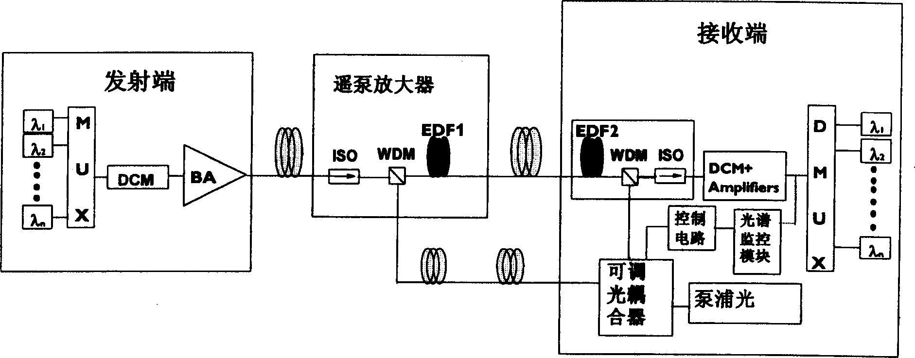
[0017] This remote pumping transmission system includes the transmitting end of the optical transmission system, the receiving end and the remote pumping amplifier in the transmission link. The remote pumping amplifier has a remote pumping source, and the transmitting end includes a multiplexer MUX and a dispersion compensation module DCM. And the power amplifier BA is connected in turn; the front end of the receiving end directly uses a section of erbium-doped optical fiber EDF2 as a preamplifier, and EDF2 can be an erbium-doped optical fiber with different doping concentrations, and the output end of the remote pumping source of the remote pump amplifier An adjustable optical coupler is connected, and the pumping light with a wavelength of 1480nm is directly divided into two paths through the adjustable optical coupler. The pump excitation of the erbium-doped fiber EDF1 in the middle; the other is used as the pump light source of the local erbium-doped fiber EDF2 connected to...

Embodiment 2

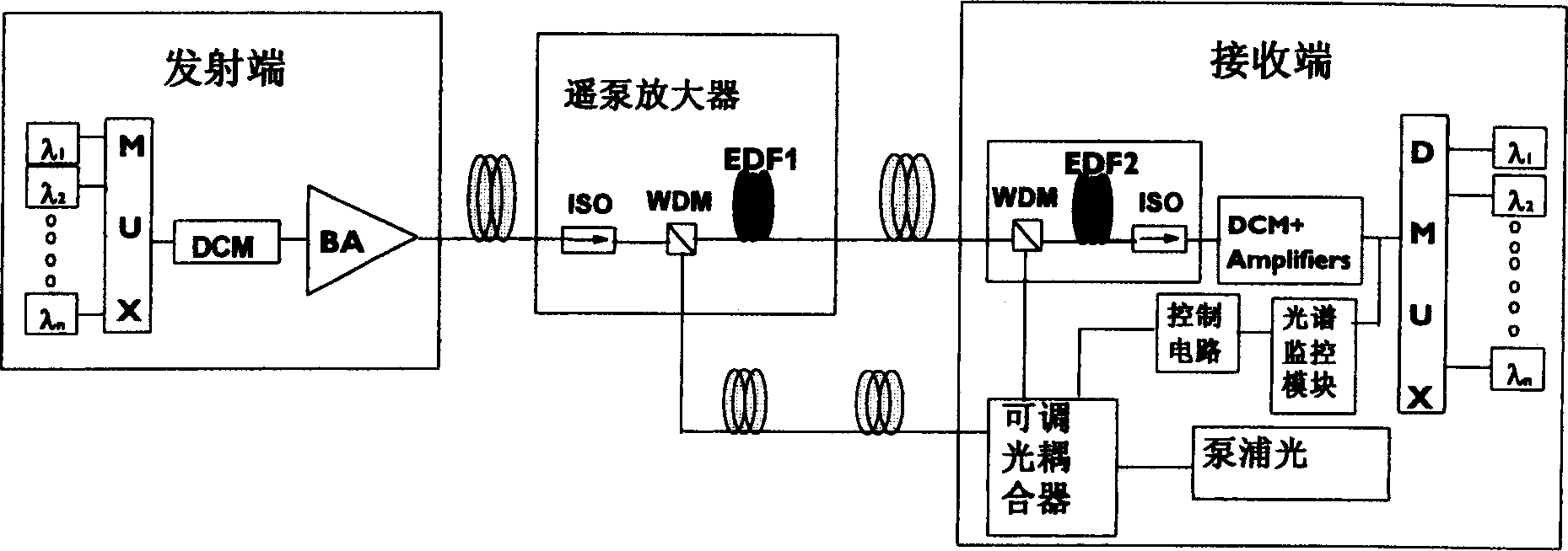
[0021] The difference between this embodiment and embodiment 1 is that, as image 3 As shown, the wavelength division multiplexer WDM is connected in front of the EDF2, and the pump light source for the local erbium-doped fiber EDF2 is forward pumped to the local erbium-doped fiber EDF2, and in embodiment 1, as figure 2 As shown, the pump light source for the local erbium-doped fiber EDF2 pumps the local erbium-doped fiber EDF2 in reverse.

[0022] As for its working principle and method, it is the same as that described in Embodiment 1, and will not be repeated here.


PUM


Abstract

A remote pump transmission system relating to electric communication technology, comprising optical transmission system a transmitting end, a receiving end and a remote pump amplifier in the transmission link, characterized by that, the receiving end has an adjustable optical coupler, the pumping light is divided into two branches after passing the adjustable optical coupler directly, one branch is used as the pumping light source as the remote pumping amplifier, the other branch is used as the pumping light source for the local erbium-doped fiber on the receiving end. The invention can exert the remote pump amplifier action to the maximum limit and perform flexible control to the system output spectrum.

Description

technical field [0001] The invention relates to electric communication technology, in particular to a remote pump transmission system. Background technique [0002] The remote pumping optical amplification technology is mainly used in the non-repeater optical transmission system to extend the transmission distance and improve the system power budget, such as figure 1 As shown, adding one or more sections of erbium-doped fiber to the signal transmission link, the pump source with a wavelength of 1480nm can be placed at the system terminal tens of kilometers away from the erbium-doped fiber, that is, the transmitting end or the receiving end, through which the signal The transmission fiber or a special fiber transmits the pump light to the erbium-doped fiber to amplify the signal light. figure 1 Among them, the remote pumping source of the remote pumping amplifier is placed at the receiving end, and the bypass backward pumping method is used, and the bypass forward pumping an...

Claims


Application Information

Patent Timeline
IPC IPC(8): G02B6/26H04B10/291
Inventor 陆洋赵福强李从奇李长春
Owner HUAWEI TECH CO LTD
Features
  • Generate Ideas
  • Intellectual Property
  • Life Sciences
  • Materials
  • Tech Scout
  • Unparalleled Data Quality
  • Higher Quality Content
  • 60% Fewer Hallucinations
Learn More