Production method of hot-dip metal strip and device therefor

A technology of hot-dip metal and manufacturing method, which is applied in hot-dip plating process, metal material coating process, coating, etc., and can solve the problems of metal strip 1 dross adhesion, lower quality, lower production efficiency, etc.

Inactive Publication Date: 2004-06-02
JFE STEEL CORP
View PDF1 Cites 7 Cited by
  • Summary
  • Abstract
  • Description
  • Claims
  • Application Information

AI Technical Summary

Problems solved by technology

Therefore, for example, for high-grade hot-dip metal strips used for automobile outer panels, countermeasures can be taken to prevent scum from adhering to low-speed operation, but this significantly hinders production efficiency
[0009] 2) The support roller 79 in the bath is often in a high-temperature and harsh environment, which is prone to malfunctions such as poor rotation. The production line must be stopped regularly to maintain or replace these rollers, so the production efficiency is reduced.
In addition, due to such failures, defects such as scum adhesion may occur on the metal strip 1.
[0010] 3) Due to the uneven rotation speed of the back-up roller 79 in the bath, uneven adhesion in the form of chatter marks occurs, which reduces the quality

Method used


Image

  • Production method of hot-dip metal strip and device therefor
  • Production method of hot-dip metal strip and device therefor
  • Production method of hot-dip metal strip and device therefor

Examples


Embodiment 1

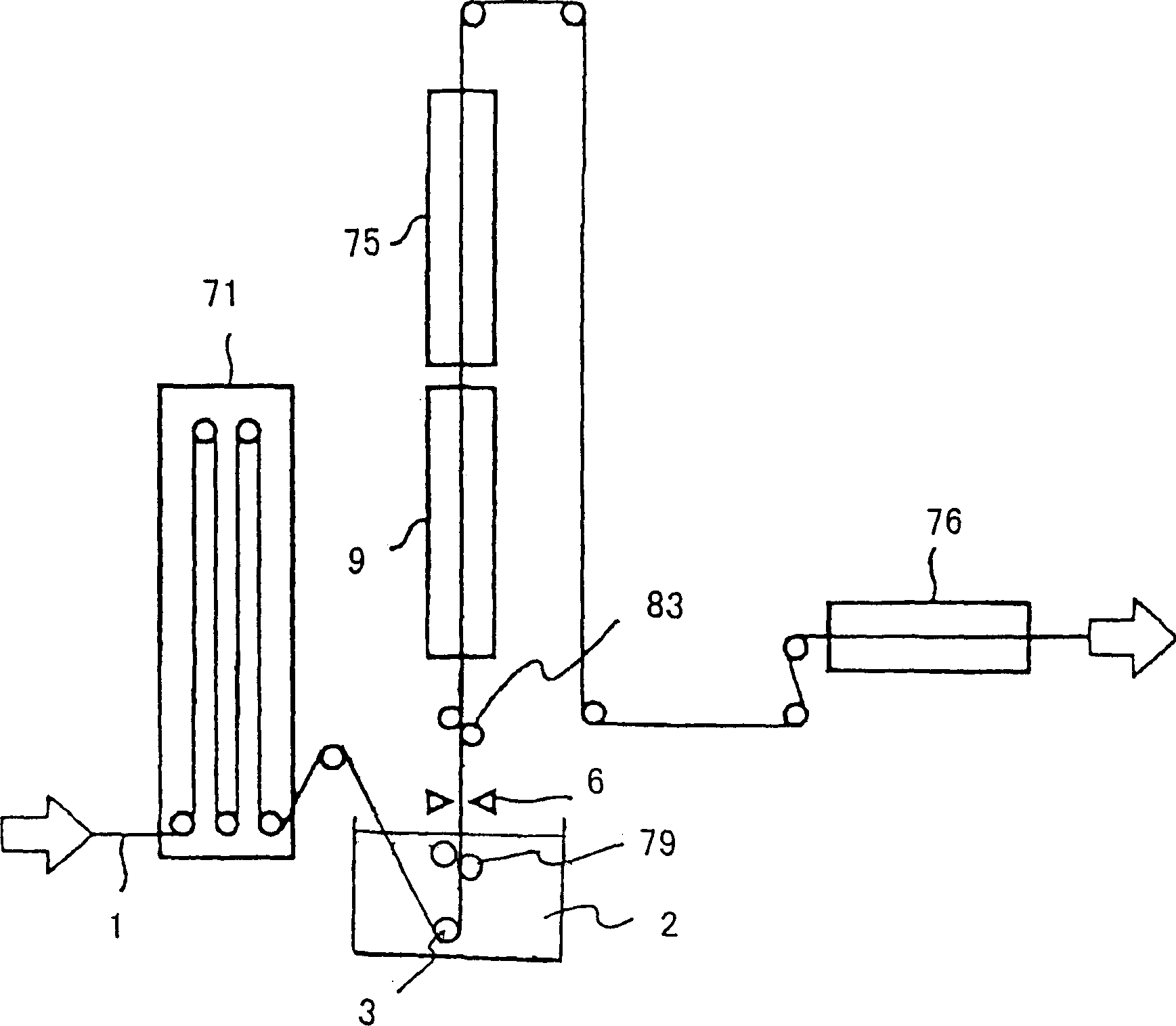
[0109] Figure 15 An example of the manufacturing apparatus of the hot-dip metal strip of this invention is shown.

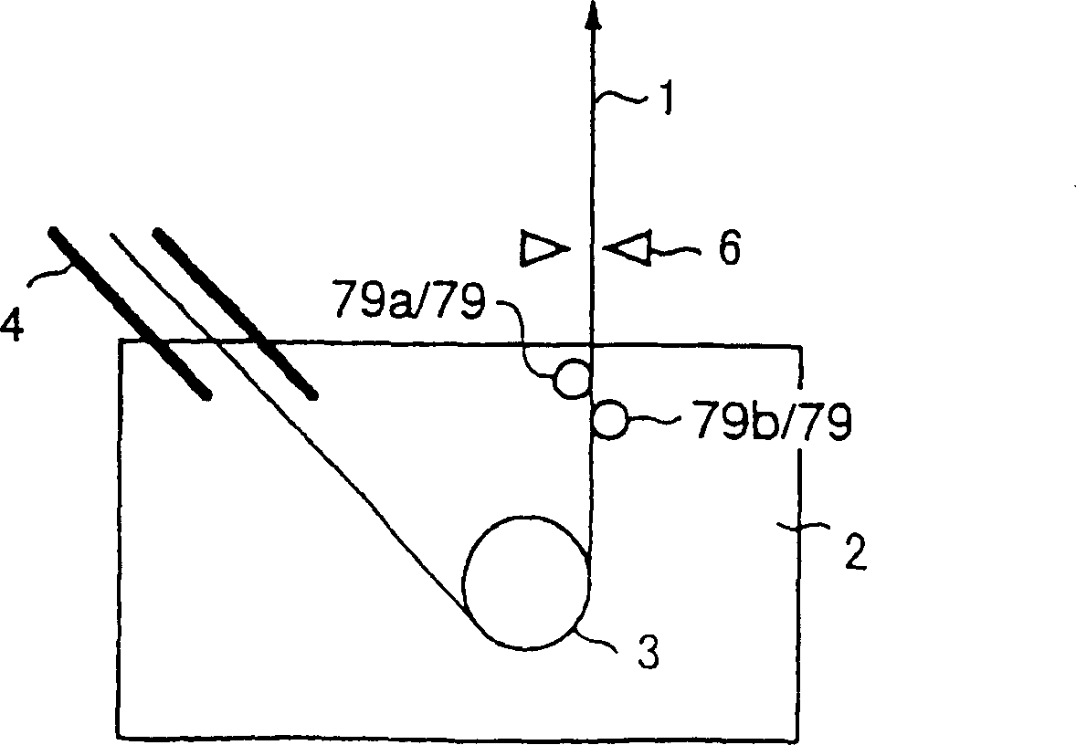
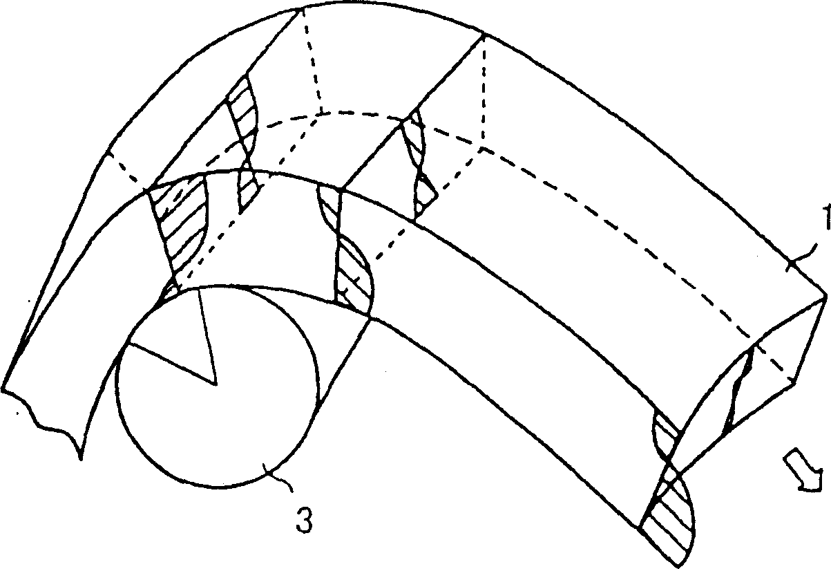
[0110] A metal strip 1 is introduced into the molten metal bath 2 from a nozzle 4 kept in a non-oxidizing atmosphere, is redirected by synchronizing rollers 3 and drawn out above the molten metal bath 2 . The amount of molten metal deposited on the plating metal adhering to the metal strip 1 while moving in the molten metal bath 2 can be adjusted by the air brush 6 .

[0111] This device does not have the support roller in the molten metal bath 2 used in the conventional device, instead, at the position immediately behind the air brush 6, a metal strip shape using magnetic force and a Vibration control device7. The position immediately behind the air brush 6 referred to here refers to a position between the air brush 6 and an alloying furnace described later. If the metal strip shape and vibration control device 7 is close to the air brush 6, better shape con...

Embodiment 2

[0114] Figure 16 Another example of the manufacturing apparatus of the hot-dip metal strip of this invention is shown.

[0115] In this device, Figure 15 The metal strip shape and vibration control device 7 using magnetic force is provided at a position immediately in front of the air brush 6 without being in contact with the metal strip 1 . The immediately preceding position mentioned here refers to the position between the molten metal bath 2 and the air brush 6 . If the metal strip shape and vibration control device 7 is close to the air brush 6, better shape control can be achieved.

[0116] When the metal strip shape and the vibration control device 7 are arranged at any position immediately in front of or behind the air brush 6, the shape of the metal strip and the vibration control effect are the same, but when they are located at the position immediately in front or immediately behind the air brush 6, respectively It has the following advantages.

[0117] When it...

Embodiment 3

[0121] Figure 17A , 17B Another example of the manufacturing apparatus of the hot-dip metal strip of this invention is shown.

[0122]In this device, two strip-shaped and vibration control devices 7 using magnetic force are provided in a non-contact manner immediately behind the air brush 6 or immediately in front of and behind the air brush 6 .

[0123] Thus, by installing a plurality of metal strip shape control devices 7, it is possible to more effectively correct the shape or suppress vibration.

[0124] Generally, when the shape is corrected, since the shape change such as warping is slow, tracking performance is not required for the shape of the metal strip and the control system of the vibration control device 7 . On the other hand, when performing vibration control, since the vibration of the metal strip 1 changes rapidly, good sensitivity is required for the control system of the metal strip shape and the vibration control device 7 . In addition, the force require...


PUM

PropertyMeasurementUnit
diameteraaaaaaaaaa
diameteraaaaaaaaaa
diameteraaaaaaaaaa

Abstract

The invention relates to a method for manufacturing a hot-dip plated metal strip comprising the steps of: introducing a metal strip into a molten metal bath of plating metal to adhere the molten metal onto the surface of the metal strip; taking out the metal strip, after turning the running direction of the metal strip, from the molten metal bath without applying external force from outside the surface of the metal strip; adjusting the plating weight of the molten metal adhered onto the metal strip; and controlling the shape of the metal strip using magnetic force in non-contact state directly before or after the step of adjusting the coating weight. The invention prevents adhesion of dross to the metal strip without degrading the productivity, and thus manufactures a high quality hot-dip plated metal strip.

Description

technical field [0001] The invention relates to a method and device for manufacturing a hot-dip metal strip. Background technique [0002] As a method of continuously electroplating a metal strip such as a steel strip, the hot-dip method is widely known, and electroplating is performed by immersing the metal strip in a bath (hereinafter referred to as a molten metal bath) in which an electroplating metal such as zinc or aluminum is melted. Compared with the electroplating method, this hot-dip method has many advantages such as being able to manufacture an electroplated metal strip at low cost, and being able to easily manufacture a thick-plated metal strip. [0003] figure 1 Shown is the production line of the past hot-dip metal strip. [0004] Rolling is carried out in the cold rolling process of the previous process, and then the metal strip 1 whose surface has been cleaned in the cleaning process is transported to the hot-dip metal strip production line. After removing...

Claims


Application Information

Patent Timeline
Patent Type & Authority Applications(China)
IPC IPC(8): C23C2/00C23C2/24C23C2/40
CPCC23C2/24C23C2/003C23C2/40C23C2/5245C23C2/00C23C2/004C23C2/00344
Inventor 壁矢和久石田匡平石冈宗浩高桥秀行石井俊夫宫川洋一蒲昭铃木克一
Owner JFE STEEL CORP
Why Eureka
Try Eureka