

Glaring-proof film
A film and light-transmitting resin technology, applied in coatings, instruments, layered products, etc., can solve the problems of reducing reflectivity, reducing surface tension, and reducing image clarity, reducing reflectivity, reducing flicker, and increasing reliability. visual effect
Inactive Publication Date: 2004-06-09
OPTIMAX TECHNOLOGY CORPORATION
View PDF6 Cites 34 Cited by
- Summary
- Abstract
- Description
- Claims
- Application Information
AI Technical Summary
Problems solved by technology
[0004] Such as the anti-glare film disclosed in U.S. Patent No. 5998013 to diffuse external light, the anti-glare film has light-transmitting particles (silicon dioxide particles) dispersed in the resin, and the anti-glare film The concave-convex shape formed on the surface (formed by different particle sizes formed by the aggregation of light-transmitting particles) diffuses the light, but because the light-transmitting particles will gather into a group (to reduce the surface tension), or be distributed as a single individual in the anti-glare Therefore, the surface roughness of the anti-glare film is increased and the particle size distribution on the surface is uneven. Therefore, when the haze (degree of light diffusion) of the anti-glare film increases, the image clarity will be reduced.
The anti-glare film disclosed in U.S. Patent No. 6074741 and No. 6164785 and U.S. Patent Application No. 2001 / 0035929A1 also has the disadvantage of increasing haze and reducing image clarity.
Moreover, the aforementioned patents do not have the feature of reducing the reflectivity to a low reflectivity level
[0005] In order to increase the diffusivity of the anti-glare film to external light, the prior art all adopts a method of enlarging the concave-convex shape of the surface of the anti-glare film (such as increasing the particle size of the light-transmitting particles), but in this way, At the same time, the haze is increased, and the image is clear and the contrast is reduced. Therefore, how to change the particle size of the light-transmitting particles (or even match the particle size of different light-transmitting particles) to improve the above shortcomings is very important.
[0006] In addition to the above method of using the light-transmitting particles on the surface of the anti-glare film to diffuse the external light to create an anti-glare effect, there is another anti-glare film that disperses the light-transmitting particles in the resin and uses the light-transmitting particles The difference in refractive index between the resin and the resin diffuses the internal light, such as: US Patent No. 6217176B1 patent case, which makes light-transmitting particles with different refractive indices scattered in the resin, and the two kinds of light-transmitting particles and the resin have different The refractive index, so the internal light can be diffused by the light-transmitting particles, or even the external light can be diffused when the light-transmitting particles are on the surface of the anti-glare film, thereby increasing the image clarity, but the same patent does not have the ability to reduce reflection The advantages of high efficiency; and such as the U.S. Patent No. 6347871B1 patent case, it is to apply the disclosure of the above-mentioned patent case, so that the two different resin layers have the effect of diffusing the internal and external light respectively, but it is in the coating However, one more step is necessary (because there are two resin layers), and it does not have the advantage of reducing reflectivity
Method used
View moreImage
Smart ImageViewing Examples

Examples
Embodiment 1
[0057] Example 1 10 13 nm 4 3.5 44 △ 160 1.5
Embodiment 2
[0058] Example 2 20 13 nanometers 2 3.5 45 ◎ 180 0.9
Embodiment 3
[0059] Example 3 10 25 nanometers 4 3.5 42 ◎ 220 1.1
Login to View More PUM
| Property | Measurement | Unit |
|---|---|---|
| particle diameter | aaaaa | aaaaa |
| particle diameter | aaaaa | aaaaa |
| particle diameter | aaaaa | aaaaa |
Abstract
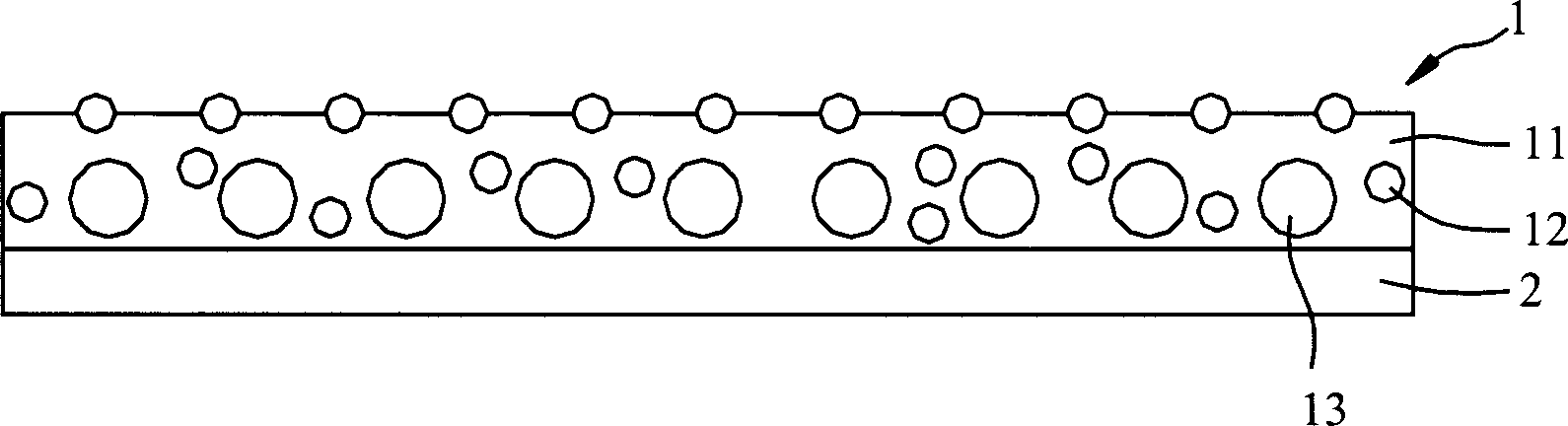
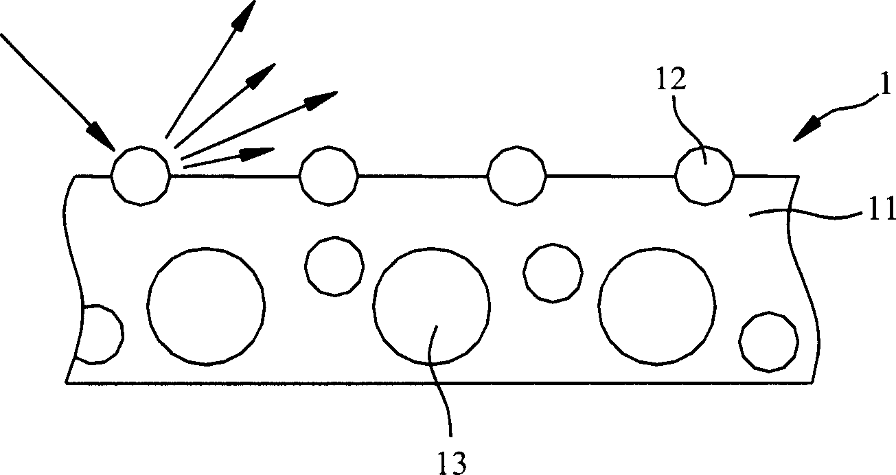
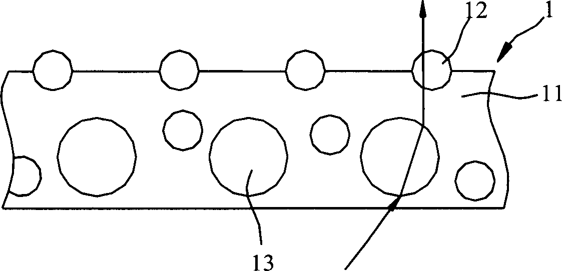
A glarofilm used in a polarizing plate and display includes a photic resin layer, a first and second photic micrograins, the first are distributed on the surface of the photic resin layer with the nm diameter between 9~500 nm, its index of refraction is same with the photic resin layer, nm grains make the surface to be fine to reduce large angle diffusion caused by too big fluctuation due to the rough surface, the second photic micrograins are scattered in the photic resin layer which index of refraction is different from the resinlayer, so the inside and outside light rays are diffused by the two photic micrograins so eyes will not feel dazzling even though the light is diffused.
Description
technical field [0001] The invention is an anti-glare film, which is applied to polarizing plates and displays (such as: displays of computers, word processors and televisions), especially an anti-glare film with high resolution to make the picture clear and has the effect of reducing reflectivity . Background technique [0002] In a transmissive display, since the internal light source will be emitted outward, if the internal light source is not diffused and continues to travel in a straight line, the user will feel the glare caused by the internal light source when visually viewing the display. Therefore, the surface of the display is often coated with a layer of anti-glare film to diffuse the light emitted from the light source inside the display. On the other hand, when the external light hits the surface of the display, if the external light is not diffused but reflected, it will be disturbed by the specular reflection light when the user looks at the display, which wi...
Claims
Login to View More Application Information
Patent Timeline
 Patent Type & AuthorityApplications(China)
IPC IPC(8): B32B27/00C08J7/04G02B1/04G02B5/02G02F1/1335
Inventor简榕震赖大王王伯萍陈宏祺
OwnerOPTIMAX TECHNOLOGY CORPORATION