Small size Low Nox gas burner equipment and method

A gas burner and burner technology, applied in the direction of gas fuel burners, combustion equipment, combustion methods, etc., can solve the problems of large burner equipment, long flame, and low regulation

Inactive Publication Date: 2004-06-23
JOHN ZINK CO LLC
View PDF0 Cites 17 Cited by
  • Summary
  • Abstract
  • Description
  • Claims
  • Application Information

AI Technical Summary

Problems solved by technology

In addition, the burner equipment hitherto used to carry out the above method is generally larger, produces a longer flame and has a lower turndown ratio

Method used


Image

  • Small size Low Nox gas burner equipment and method
  • Small size Low Nox gas burner equipment and method
  • Small size Low Nox gas burner equipment and method

Examples


Embodiment 1

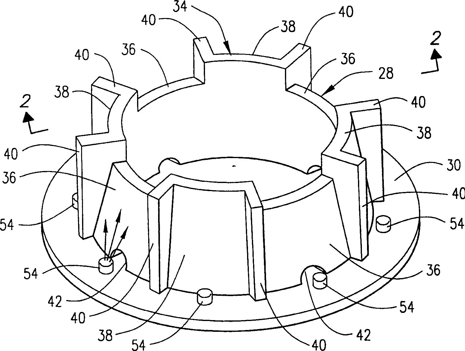
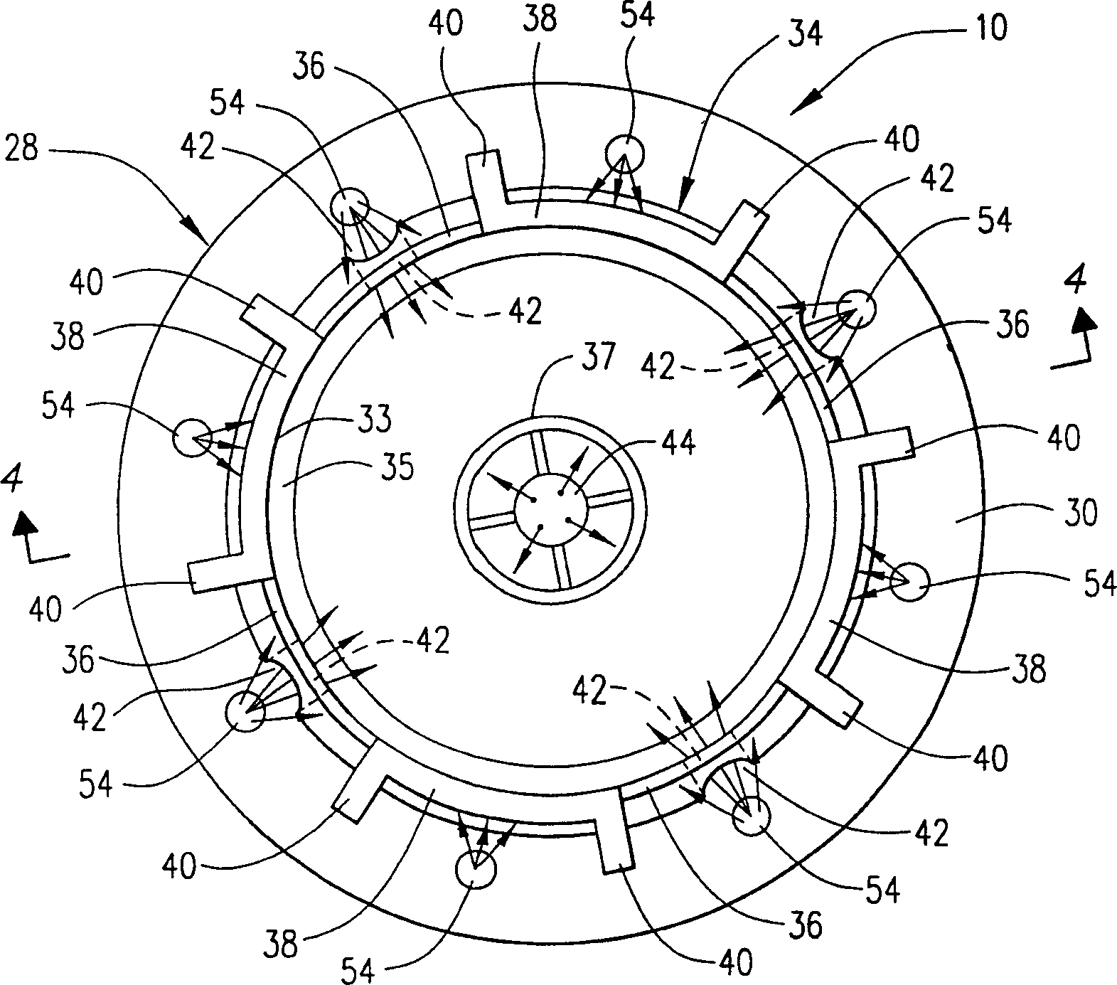
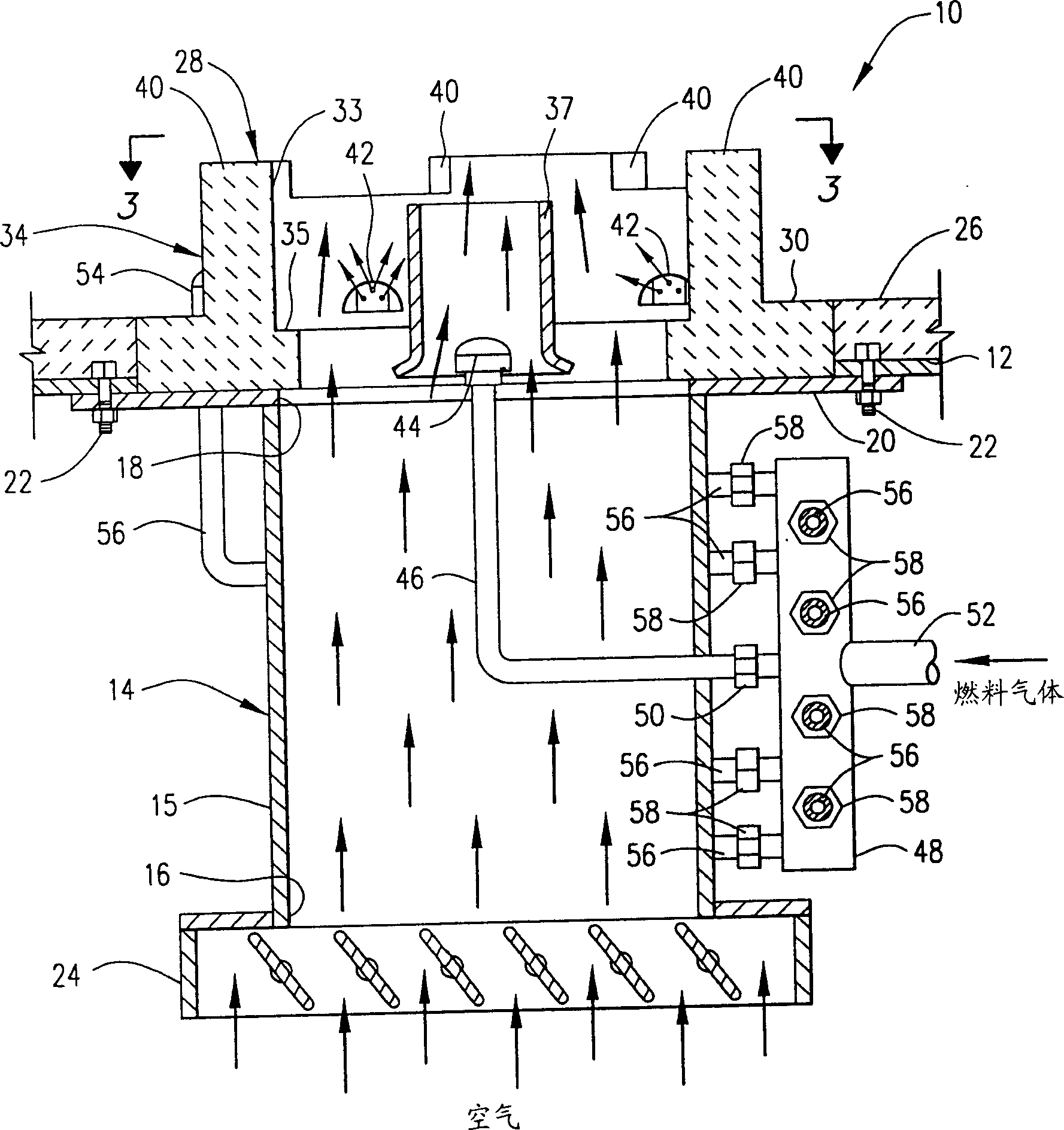
[0035] The burner device 10 is designed to release 8 million BTU of heat per hour by burning natural gas with a calorie value of 913 BTU / SCF, so that the burner device 10 is burned into the furnace space. The pressurized fuel gas is supplied to the pipe 48 of the combustor 10 at a pressure of approximately 33 psig and a flow rate of approximately 8765 SCF / hour. The 20% volume part (1753SCF / hour) of the fuel gas is used as the first fuel gas and is discharged into the hole 32 and the burner tile 28 through the fuel gas discharge nozzle 44 and through the fuel gas discharge nozzle 54. The fuel gas discharges The nozzle 54 is arranged near the hole 42 in the wall 40 of the burner tile 28. The remaining part of the fuel gas (ie, the second part) is discharged into the furnace space at a rate of 7012 SCF / hour through the nozzle 54 as a separate fuel gas stream mixed with the exhaust gas.

[0036]The rate of air introduced into the furnace space through the air conditioner 24, the housi...

Embodiment 2

[0038] In order to see the flame pattern produced by the burner device 10 while operating as described in the above embodiment 1, a computer simulation program was used. The software used can be obtained from Fluent Inc. Of Lebanon, New Hampshire, USA. In the simulation program, the burner design can be reconstructed in all three-dimensional details, including all important features such as tile surface, fuel gas perforation, flame stabilizer tile shoulder and complete air chamber structure.

[0039] The three-dimensional model of the furnace in which the burner equipment was tested was installed in the furnace model, except that the air entered from the side instead of from the bottom. The furnace model was exactly the same as the test burner and furnace used in Example 1. . The finite volume method is used to divide the flow space in the combustor model into many small volumes, and boundary adjustments such as fuel pressure, flow rate, etc. are used at the inlet of the combustor...


PUM


Abstract

Compact low NOx gas burner apparatus and methods for discharging fuel gas and air mixtures into furnace spaces wherein the mixture is burned in folded flame patterns and flue gases having low NOx content are formed are provided. A burner apparatus of the invention is basically comprised of a housing having a burner tile attached thereto and means for introducing air therein. The burner tile has an opening therein with a wall surrounding the opening which extends into a furnace space. The exterior sides of the wall are divided into sections by radially positioned baffles with alternate sections having the same or different heights and slanting towards the opening at the same or different angles. Primary fuel gas mixed with flue gases and air is discharged through the burner tile. Secondary fuel gas is discharged adjacent to the external slanted wall sections whereby the secondary fuel gas mixes with flue gases in the furnace space. The resulting fuel gas-flue gases streams mix with the fuel gas-flue gases-air mixture discharged through the burner tile and the resulting mixture is burned in the furnace space.

Description

Technical field [0001] The present invention relates to a gas burner device and method for combusting a fuel gas-air mixture and the resulting exhaust gas with a low NOx content. Background technique [0002] The competent government departments have been constantly proposing emission standards. These standards impose restrictions on the gaseous pollutants emitted into the atmosphere such as nitrogen oxides (NO x ) Is limited. These standards have led to the development of various NO reduction x Improved gas burner for the generation of and other exhaust gas. For example, methods and equipment have been developed in which all air and some fuel are burned in a first zone and the remaining fuel is burned in a second zone. In this method of staged refueling, the excess air in the first zone is used as a diluent, which reduces the temperature of the combustion gas and therefore reduces NO x Formation. Other methods and equipment have been developed in which exhaust gas is combined wi...

Claims


Application Information

Patent Timeline
Patent Type & Authority Applications(China)
IPC IPC(8): F23D14/02F23C6/04F23C9/00F23C99/00F23D14/70F23D14/84
CPCF23C9/00F23D14/70F23C2202/20F23C6/047F23D14/02
Inventor 钟一萍耶西·史蒂文·钱伯斯卡罗尔·安·斯基尼朋罗杰·L·波雅万特·D·贾亚卡尔理查德·T·韦贝尔迈克尔·G·克拉克斯顿玛丽安·兹莫拉达林·罗伯特·福特
Owner JOHN ZINK CO LLC
Why Eureka
Try Eureka