Razor blade

A technology of blades and razors, applied in the field of razor blades, which can solve problems such as limitations, inability to shave beard or hair smoothly, and difficulty in obtaining the radius of the blade tip

Inactive Publication Date: 2004-07-07
MATSUSHITA ELECTRIC WORKS LTD
View PDF2 Cites 4 Cited by
  • Summary
  • Abstract
  • Description
  • Claims
  • Application Information

AI Technical Summary

Problems solved by technology

However, since the edge of the grid blade made of metal material is formed by machining, it is limited to form an edge with a small nose radius.
For example, it is difficult to obtain a nose radius of 1 μm or less even if fine grinding such as polishing is used to remove the burr generated on the blade due to grinding
For this reason, mesh blades made of stainless steel have not been able to shave beard or hair smoothly unless a razor blade with a straight edge with a tip radius of about 0.1 μm obtained by grinding stainless steel sheets is used
Also, in conventional razor blades on the market, the technology to form a cutting edge with a nose radius of 0.1 μm or less has not been fully formed

Method used


Image

  • Razor blade
  • Razor blade
  • Razor blade

Examples


Embodiment 1

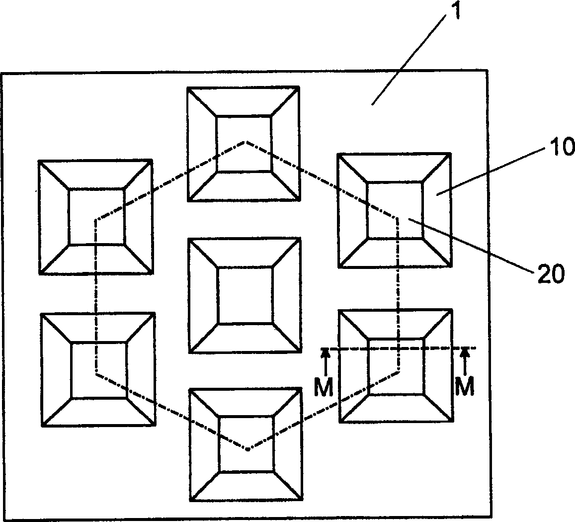
[0035] A polycrystalline silicon block with a grain size of about 10mm is cut into a 0.3mm thick 7mm×7mm square sheet-like monocrystalline silicon. Then, by chemical etching, follow Figure 1A The pattern shown forms a plurality of square openings (blade openings) measuring 1.5mm x 1.5mm. Next, a blade 10 is formed in each opening 20 by using an argon ion beam etching technique, the blade angle is 20°, and the blade protrudes into the opening 20 . In this embodiment, the blades 10 are formed on all four sides of the square opening 20 . The center-to-center distance of adjacent blade openings is 2.0 mm. The blade openings are arranged in the same plane for the closest packing. Such as Figure 1A As shown by the dotted lines, the centers of the three adjacent openings are set at the vertices of an equilateral triangle with a side length of 0.7 mm.

[0036] Observing the cutting edge 10 of the obtained razor blade 1 through a scanning electron microscope, it can be confirmed t...

Embodiment 2

[0038] A polycrystalline silicon block with a grain size of about 10mm is cut into a 0.3mm thick 7mm×7mm square sheet-like monocrystalline silicon. Then, by chemical etching, follow figure 2 The pattern shown forms a plurality of rectangular openings (blade openings) measuring 1.5mm x 5mm. Next, by using an argon ion beam etching technique, a blade 10 is formed in each rectangular opening, the blade angle is 20°, and the blade protrudes into the rectangular opening 20 . In this embodiment, the blades 10 are formed on all four sides of the rectangular opening. The center-to-center distance between adjacent openings is 2.0 mm.

[0039] Observing the obtained edge 10 of the razor blade through a scanning electron microscope, it can be confirmed that the edge radius (R) of the edge is less than 10 nm. As in the case of Example 1, in the case of cutting one hair, the cutting resistance of the razor blade in Example 2 was compared with that of a commercially available razor blad...

Embodiment 3

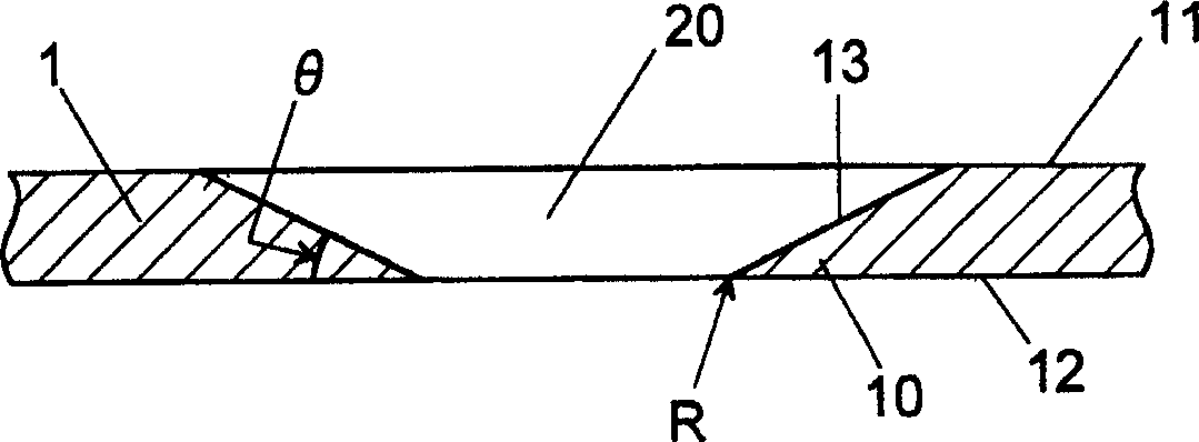
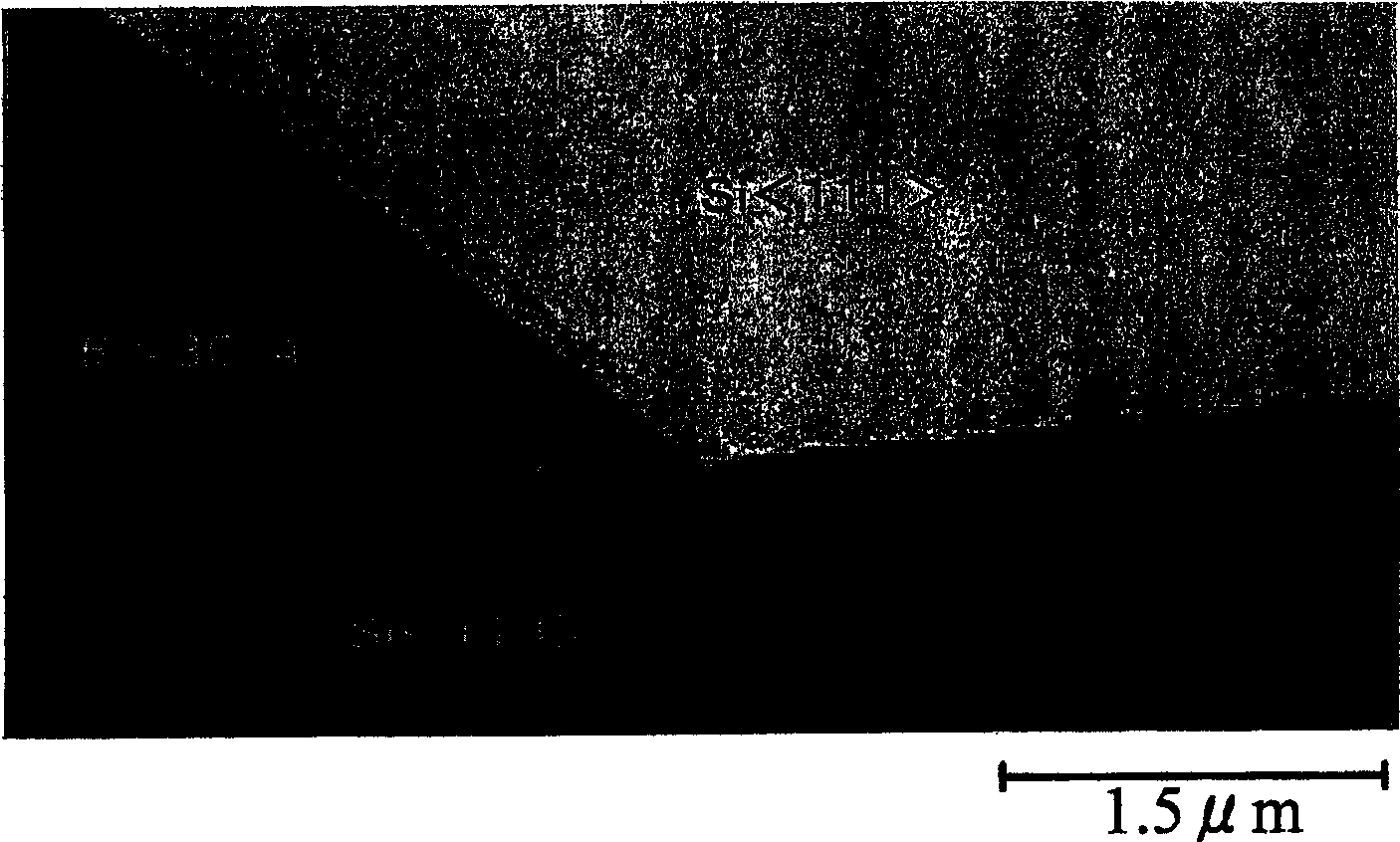
[0041] A silicon wafer with a thickness of 0.3 mm was obtained by cutting a (110) monocrystalline silicon block into a thin slice. then press Figure 1A In the pattern shown, a square opening (blade opening) with a size of 1.5 mm x 1.5 mm was formed by chemically etching (selective etching) the (111) plane. In this embodiment, through the intersection of (110) plane and (111) plane ( Figure 1C ) obtained a cutting edge 10 with a cutting edge angle of 35.4°. Observing the obtained edge 10 of the razor blade through a scanning electron microscope, it can be confirmed that the edge radius (R) of the edge is less than 10 nm. In the case where the razor blade cuts a single hair, the cutting resistance is 3 grams force. And use the razor blade that has the blade angle of about 20 ° on the market now, the cutting resistance of cutting a hair is 10 grams force. Therefore, the cutting resistance of the razor blade shown in Example 3 is lower than that of the razor blades on the mar...


PUM

PropertyMeasurementUnit
radiusaaaaaaaaaa
radiusaaaaaaaaaa
diameteraaaaaaaaaa

Abstract

A razor blade which is smaller in cutting resistance to objects of cutting such as hair and beard than conventional blades, and is improved in safety when in use. This razor blade is obtained by using as a silicon thin sheet a single crystal Si material such as an Si wafer or a polycrystalline Si material containing comparatively large Si crystal particles, forming at least one opening in this silicon thin sheet by chemical etching, and then, without depending on machining, using ion beam etching to form an Si single crystal blade point projecting into the opening so that a nose radius is 0.5 [mu]m or smaller, preferably 0.1 [mu]m or smaller.

Description

technical field [0001] The present invention relates to a razor blade which is excellent in safety and cutting performance when cutting objects such as beard, hair, etc., particularly, this razor blade has a cutting edge made of single crystal silicon and has a very Small nose radius (nose radius). Background technique [0002] A conventional razor blade has a cutting edge formed in line along one side of a thin steel sheet, and during use, the conventional razor blade occasionally cuts the skin. Therefore, it is very important to improve its security. For example, it has been proposed to wind multiple coils of thin metal wire at regular intervals on a razor blade to reduce damage to the skin. However, although good cutting performance is maintained when cutting objects such as beards and hairs, a satisfactory level cannot always be obtained from the viewpoint of improving safety. [0003] Additionally, various net blades have been proposed for better security. For examp...

Claims


Application Information

Patent Timeline
Patent Type & Authority Applications(China)
IPC IPC(8): B26B21/38B26B21/56B26B21/58
CPCB26B21/38B26B21/58B26B21/56
Inventor 滨田纠藤本真司佐近茂俊小财敬
Owner MATSUSHITA ELECTRIC WORKS LTD
Why Eureka
Try Eureka