Process for recovery of oil from natural oil reservoir

A natural oil layer and natural gas technology, applied in the field of oil exploitation, can solve the problems of large energy and consumption

Inactive Publication Date: 2004-07-14
南非石油和天然气(私人)有限公司 +1
View PDF1 Cites 10 Cited by
  • Summary
  • Abstract
  • Description
  • Claims
  • Application Information

AI Technical Summary

Problems solved by technology

Such a device also consumes a lot of energy

Method used


Image

  • Process for recovery of oil from natural oil reservoir
  • Process for recovery of oil from natural oil reservoir
  • Process for recovery of oil from natural oil reservoir

Examples


Embodiment Construction

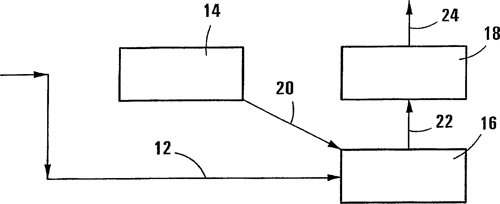
[0074] Referring to the drawings, Figure 1 depicts a process for enhancing oil recovery using compressed natural gas. FIG. 1 schematically shows a natural gas flow pipeline 12 , a power plant 14 , a compressor 16 and an oil field 18 . Power plant 14 supplies power to compressor 16 , which is injected with natural gas via flow line 12 as generally indicated by arrow 20 . The compressed natural gas is then transported from compressor 16 via flow line 22 to oil field 18 where it is used to increase the production of crude oil, generally indicated by arrow 24 .

[0075] The natural gas is compressed in compressor 16 to 105 bar absolute (1525 psi absolute) before being piped to field 18 . The power plant 14 is a gas powered plant that uses 378 million standard cubic meters (1336MMscfd) of natural gas per day and consumes 394 megawatts (528,000hp) of electricity to drive the compressor 16 .

[0076] Over a design life of fifteen years, it is estimated that the operation will produ...


PUM


Abstract

A method for recovering oil ( 24 ) from a natural oil reservoir ( 18 ) includes the steps of separating air to produce an oxygen rich stream ( 40 ) and a nitrogen rich stream ( 34 ), providing a natural gas stream ( 12 ) and feeding at least part of the oxygen rich stream ( 40 ) and the natural gas stream ( 12 ) into a gas to liquid or GTL conversion installation ( 42 ) to produce hydrocarbon products ( 44 ) and heat. The heat produced in the gas to liquid conversion installation is used to produce energy ( 20 ) to pressurize ( 16 ) the nitrogen in the nitrogen rich stream ( 34 ) to produce a pressurized nitrogen rich stream ( 22 ). The pressurized nitrogen rich stream ( 22 ) is passed into a natural oil reservoir ( 18 ) to enhance the recovery of oil ( 24 ) from the reservoir.

Description

technical field [0001] This invention relates to methods of recovering petroleum from natural reservoirs or wells. Background technique [0002] For the purposes of this specification, a gas-to-liquid or GTL conversion unit is a unit that converts streams of oxygen and natural gas primarily to hydrocarbon products and water, with the by-production of heat. [0003] Crude oil is extracted from oil-bearing reservoirs underground by allowing the downhole pressure naturally present in the reservoir to pressurize the liquid through wells drilled into the oil field to the surface. However, enhanced oil recovery techniques are used to improve or maintain oil production when downhole pressure is insufficient to force oil to the surface. The simplest of these techniques is to pump water into the reservoir through the injection system to maintain or increase the pressure in the field. In some cases, water flooding is not the most effective EOR technique and it is better to maintain ...

Claims


Application Information

Patent Timeline
Patent Type & Authority Applications(China)
IPC IPC(8): E21BE21B43/16F25JF25J3/04
CPCF25J3/04569F25J3/0403E21B43/168F25J3/04539F25J3/04521F25J3/04121
Inventor 葛瑞·达维特·亨特利·萧罗杰尔·琼森
Owner 南非石油和天然气(私人)有限公司
Why Eureka
Try Eureka