High-accuracy single F-P plate angular displacement measurement instrument
A displacement measurement, high-precision technology, applied in the field of high-precision single F-P plate angular displacement measuring instrument, can solve the problem of difficult high-precision angular displacement measurement, and achieve the effects of improving measurement accuracy, reducing measurement errors, and enhancing anti-interference ability.
- Summary
- Abstract
- Description
- Claims
- Application Information
AI Technical Summary
Problems solved by technology
Method used
Image

Examples
Embodiment Construction
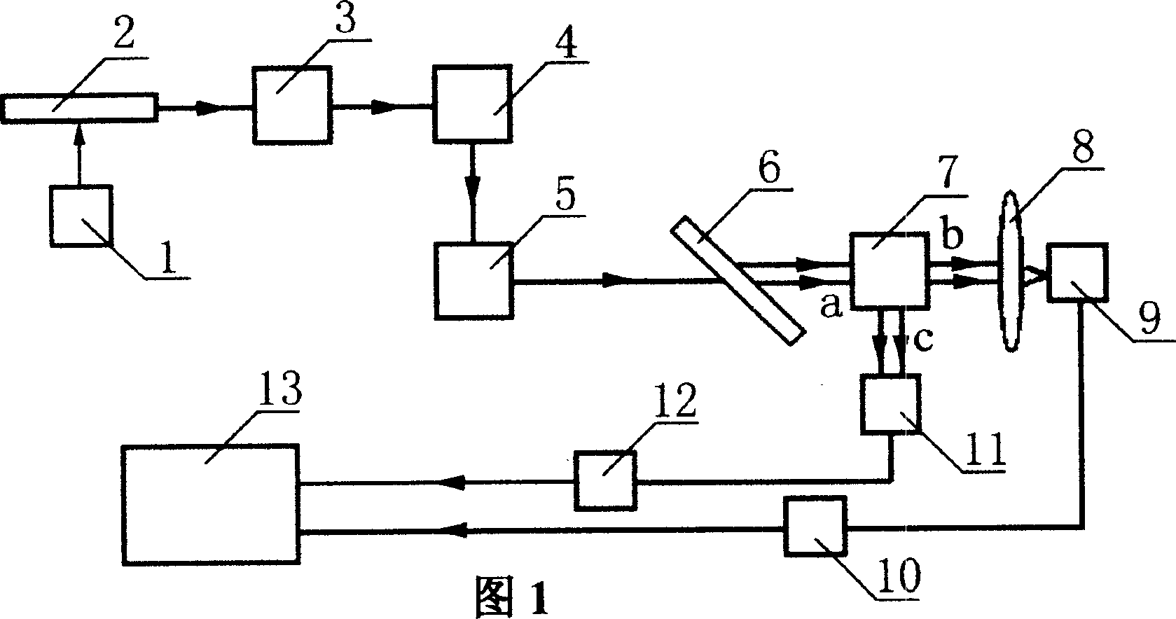
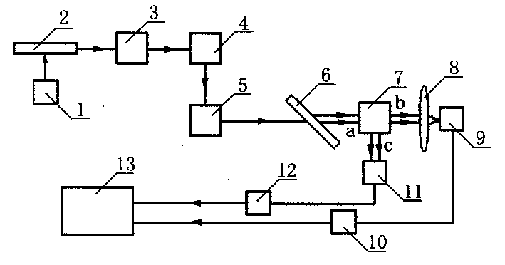
[0019] Please refer to Fig. 1, Fig. 1 is a structural diagram of a high-precision single F-P plate angular displacement measuring instrument of the present invention. The high-precision single F-P plate angular displacement measuring instrument of the present invention comprises: a modulated light source 2 with a drive power supply 1, a beam collimating objective lens 3 and a reflector 4 are arranged along the advancing direction of the light beam emitted by the modulated light source 2, An object 5 to be measured is placed in the advancing direction of the reflected light beam from the mirror 4 . An F-P plate 6 and a beam splitter 7 are placed in the advancing direction of the reflected light from the measured object 5 . A lens 8 and a photoelectric conversion element 9 are arranged in the direction of the transmitted light beam at port b of the beam splitter 7 , and the photoelectric conversion element 9 is connected to an analog-to-digital conversion element 10 connected to...
PUM
 Abstract
Description
Claims
Application Information